 Facebook
 Google
 GitHub
 Linkedin
Hello guys...
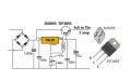
I am planning to make a dual voltage regulated power supply 6A +35 0 -35V
I was searching google and i stumble with this design…
My question is…
1. Whats is the purpose of transistor?
2. Is this design effective?
Interesting design, makes me want to use this in a dual voltage.
3. Can anyone pls give me a dual voltage design?
Thank you guys..
Attachments
-
 77 KB Views: 41


