The calculated average current draw from you battery is about 1000mAH / 24 ≈ 40mA. A 1N5817 1A Schottky diode has a forward drop of about 0.3V at 40mA giving a power loss of 0.3V * 50ma =12mW. This is about 8% of the 3.7V * 40mA = 148mW the battery is supplying.
The calculated average current draw from you battery is about 1000mAH / 24 ≈ 40mA. A 1N5817 1A Schottky diode has a forward drop of about 0.3V at 40mA giving a power loss of 0.3V * 50ma =12mW. This is about 8% of the 3.7V * 40mA = 148mW the battery is supplying.
Not likely. Mosfets don't work very well at 3.7 volts, you would need one for each battery, and you would need a control circuit...all of this using less than the unacceptable 12 milliwatts.
The problem is preventing the higher voltage battery from charging the other battery going dead. Without a diode you will need a complex circuit to detect the direction of current flow through the battery, such as a Hall Effect device, and then control a MOSFET switch to shut off the flow to the lower voltage battery. It would be difficult to do all that for less than 12mW of power.
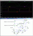
Here's a reasonably simple circuit that should do what you want. It uses two P-MOSFETs to switch the battery with the highest voltage to the load. The first comparator compares the two battery voltages and turns on the MOSFET (connects the gate to ground) that has the highest battery voltage. The second comparator is used to invert the signal so the opposite MOSFET is turned off. The comparator's supply voltage is from the two diodes, D1 and D2 so that the highest battery voltage is always powering the comparators.
The 3MΩ feedback resistor on U1 provides about 50mV of hysteresis so the circuit doesn't oscillate between the two batteries if their voltages are close. You can increase the hysteresis, if necessary, by reducing the resistor value.
Note that the MOSFETs are connected with the drain side to the battery. This is to prevent the load voltage from charging the battery of the disconnected side through the MOSFET parasitic diode. MOSFETs conduct equally well in either direction so it's not a problem that the normal load current direction is from drain to source, opposite the usual for a P-MOSFET.
The P-MOSFETs can be any 2.5V logic level (not threshold voltage) P-MOSFETs with 100mΩ or less ON resistance at 2.5V Vgs.
LM339 quad comparators are shown but you can use the LM393 dual comparator to save the power supply current from the unused comparators. They work down to 2V supply voltage.
The simulated circuit current was ≈350μA, which is only about 0.9% of the load current.
Wouldn't this tend to oscillate due to the load pulling down the voltage of the battery being used? I suppose the comparator hysteresis could be increased as noted to compensate, but if the load is big enough, I'm not sure you could stop the oscillation.
Here's a reasonably simple circuit that should do what you want. It uses two P-MOSFETs to switch the battery with the highest voltage to the load. The first comparator compares the two battery voltages and turns on the MOSFET (connects the gate to ground) that has the highest battery voltage. The second comparator is used to invert the signal so the opposite MOSFET is turned off. The comparator's supply voltage is from the two diodes, D1 and D2 so that the highest battery voltage is always powering the comparators.
Wouldn't this tend to oscillate due to the load pulling down the voltage of the battery being used? I suppose the comparator hysteresis could be increased as noted to compensate, but if the load is big enough, I'm not sure you could stop the oscillation.
Oscillations are possible, so you would just need to increase the hysteresis. In this case the load is only 40mA so a high value of hysteresis should not be needed.
I missed that, and I was thinking of a larger load. It should work nicely when the load is small compared to the capacity of the batteries involved. It might be a good solution for some of the requests around here for ORing power supplies together.

 Facebook
 Google
 GitHub
 Linkedin