Facebook
 Google
 GitHub
 Linkedin

I am very interested in the topic of shoot-through, and how to drive power FETs from microcontrollers.By shoot through, I'm assuming you're talking about the time when the NMOS and the PMOS are both on? That's why, my original question was asking are there any good NMOS & PMOS transistor combo's that have pretty identical Vt's.
Specifically, I'm trying to use the inverter as a driver from A PWM output from PIC micro controller (0-5V PWM, 25mA max output) which is going to drive 4 power mosfet's. The four power mosfets are turning on / off 30 amp load. I shouldn't need more than one amp from the driver to charge the four power mosfets gate capacitance's.
Let me make some comments with my 2 cents, and then I hope to learn from surfline and others. That is why I am bumping this thread, to continue to learn about this.
In your first paragraph you say you want a NMOS and PMOS combo with near identical Vg(th). These are definitely available, if you search Digikey for MOSFET arrays and select "N and P". But what I really think you want is to get a pair of FETs where each Vg(th) is more than half the swing of your signal. In this case, 5V is your signal swing so you want something with threshold above 2.5V (or below -2.5V for the PMOS). If you get something with a 1V threshold, then you'll have a whole 3V from 1V to 4V where both FETs are somewhat on. Does that sound right to you?
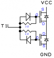
My recommendation for making a power FET drive using the 5V microcontroller is to separately drive the gate of the N and the P driver MOSFETs. This way, you can turn off one FET, then in the next instruction cycle, you can turn on the other one. There will be no overlap, and a very short delay where the output is not driven. If the output is driving the gate of a power FET, then it should be fine to have it high impedance for a couple microseconds -- it will just stay where it is since it's a capacitor.
My last thought on shoot-through is that if the power & speed of the drive is not important, then it is okay to put a resistor between the drains of a CMOS pair. This way, the shoot-through will be limited by the resistor. Maybe 100 Ohm or 1000 Ohm depending on the application. For slower signals this is often okay.
Look forward to comments.