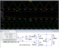
Here's the sim of ronsimpson's Post #38 suggested circuit with a 2N2222 transistor that limits the peak LED current to about 20mA:
After the peak current, the transistor draws only a few nA otherwise.
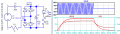
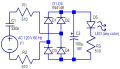
That circuit in post #41 uses a series current limiter to limit the LED current from a rectified mains supply. R1 and C1 serve to limit the current into the bridge rectifier. Transistor Q1serves as a current regulator to limit LED current.
That circuit is "rather scary" in my opinion. Almost every connection is at a shock hazardsous voltage. YES, it would work, but !
Certainly, so it must be isolated so no one can touch the circuit when in the system.
And obviously precautions must be used when testing the exposed circuit.
At it minimum it should be plugged into a GFIC socket so a single-point touch of the circuit won't be lethal.
Rather scary is also when a grounded scope probe gets connected to the circuit.
Rather scary is when Line and Neutral are wrong. I have seen that too much.
I have made products with almost this circuit, but it is inside an insulated case.
Rather scary is also when a grounded scope probe gets connected to the circuit.
Rather scary is when Line and Neutral are wrong. I have seen that too much.
I have made products with almost this circuit, but it is inside an insulated case.
My point was that with the potential hazard, any people who choose to copy that circuit need to be cautioned about the hazard. While most of the folks seeing it would see that and be careful, there may be a newcomer lacking that insight. THAT is the reason for my comment. My second, more important advice is that if one does not already know how to do it, DO NOT EVEN think about TRYING TO CONNECT IT!!
There are already mains poweredindicator lights avaiable that are safety certified!
In addition, a whole lot of important information about this potential application is missing. By far, the safest scheme is to use a step-down transformer to provide isolation.
Using a scope on a non-isolated mains connected circuit is usually a very poor choice. THAT is why we have isolation transformers, or we use battery powered scopes.
For 120VAC, don’t connect a normal LED directly to the mains. Use a proper AC-rated LED indicator module or an isolated driver with the correct resistor/rectifier setup. For 24VAC, you can use a suitable LED indicator rated for 24VAC or a small bridge rectifier with a current-limiting resistor. Make sure the LED voltage/current ratings match the supply.
Somebody should invent a full wave rectifier LED module; all in one single package with just four leads. Wouldn't be a good product for novice electronics hobbiest's though.
Somebody should invent a full wave rectifier LED module; all in one single package with just four leads. Wouldn't be a good product for novice electronics hobbiest's though.
That would actually be a pretty interesting idea. A 4-lead module with the bridge rectifier, current limiting, and LED array all built in would make AC-powered LED projects much simpler — basically just connect AC in and get DC LED output.
The challenge is that it would hide a lot of the important design choices: voltage rating, heat dissipation, flicker, current regulation, and safety isolation. For beginners, it might encourage people to connect things incorrectly without understanding what is happening.
For experienced hobbyists, though, a compact "AC LED brick" could be very handy for quick prototypes, indicators, and retrofits. It’s surprising something like that isn’t more common, since the parts already exist separately.
The challenge is that it would hide a lot of the important design choices: voltage rating, heat dissipation, flicker, current regulation, and safety isolation. For beginners, it might encourage people to connect things incorrectly without understanding what is happening.
What I had in mind was something consisting of just four LED's and the leads. Externally one would have to decide on the voltage and the current to be used. That's why I said it'd be good for experienced hobbiest's.
Somebody should invent a full wave rectifier LED module; all in one single package with just four leads. Wouldn't be a good product for novice electronics hobbiest's though.
Mains powered "LED lights" are already commercially available, even at the "Home Depot" stores. But, since it is a given that LEDs do not last "forever", I have avoided them.
AND, while using a series capacitor for a current limiting mains voltage droping" application can work, I would never ever use it in any design tracable back to me, due to liability issues. Capacitor leakage can cause some serious problems.
I was talking about one of these - only instead of being solid blacked out I was thinking of something like this that had the ability to deliver visible light.
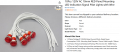
But admittedly there ARE LED indicator lights that have built in rectification. I recently used 12V LED indicators whose polarity didn't matter. Either way you hooked them up to 12 volts DC - they illuminated. By way of extension, you can power them from 12VAC with no harm. So they have built-in rectification and current control, since they're designed for 12V operation. https://www.amazon.com/dp/B088KC6BP4
12V, 24V, 110V are all available.
@Danko The AliExpress indicators do not say they're compatible with AC. If they can be 110 - 220V I'd make an assumption that they are able to be powered from an AC source. However, the picture shows indicators with one red and one black wire. In that case I'd assume they are not AC source capable but can only be used as DC sourced indicators. Do you know if they can be used on AC sources? The AliExpress link shows information in a language I don't know, can't read.
The pictures do lead to confusion, no question about that! But this would not be the first time that I have seen AN ACTUAL ERROR in a posting on line. I recall seeing a fantastic deal, a 100 amp 12 volt DC wall wart, for a very good price. The copywriter simply did not understand the prefix "miili" in front of the "amps" notation of the current.

 Facebook
 Google
 GitHub
 Linkedin