Drive relay with output from voltage converter

Thread Starter

carlosc

Joined Feb 2, 2018
24
Hello! This is my first post here. I will start by saying that I don't know a lot about electronics and electricity so forgive me if I say something that does not make sense.

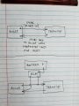
I am trying to figure out how to drive a relay with the output of a voltage converter. Please take a look at the diagram attached. The top part shows my current setup for converting the 24VAC voltage from the source I am working with (the boiler in my basement) to 3.3VDC. I'm using a voltage converter I found online and it's working perfectly (checked the output voltage with a multimeter). I am converting the voltage to 3.3VDC because that's the voltage I need to drive the relay I am working with and also feed that voltage into one of the pins in the Raspberry Pi. Please note that the 24VAC source won't always be providing voltage but the rest of the system must still stay on.

The bottom part of the diagram shows my Raspberry Pi setup. I have an AC adapter that powers the Raspberry Pi with 5VDC through the mini USB port on the Raspberry Pi. I also have a Sainsmart relay that is connected to the Raspberry Pi through the 5VDC pin and the ground pin. Using a GPIO pin, I can control the relay by turning the GPIO pin to high or low (3.3VDC or 0VDC).

My project requires that the relay be controlled by the presence or absence of voltage from the 24VAC source. I am having a hard time finding a way to make that happen given that there are 2 wires coming out of the voltage converter and that I only have one control pin on the relay.

What do I need to do to make this work? 20180202_161818.jpg
 

crutschow

Joined Mar 14, 2008
34,284
I am having a hard time finding a way to make that happen given that there are 2 wires coming out of the voltage converter and that I only have one control pin on the relay.
The relay also has a ground pin which goes to the voltage converter common.
 

Thread Starter

carlosc

Joined Feb 2, 2018
24
The relay also has a ground pin which goes to the voltage converter common.
Here's a picture of the relay. I have the 5v pin from the Raspberry Pi connected to the VCC pin on the relay (the one all the way to the right) and the ground pin from the Raspberry Pi connected to the GND pin (the one to the left of the IN1 pin).

Are you saying that I should the converter's output ground to the other ground pin on the relay (the one on the left side to the right of VCC) ?

For my learning, what did you mean by "common"? 20180203_000326.jpg
 

crutschow

Joined Mar 14, 2008
34,284
Okay. That circuit energizes the relay by having a plus voltage on Vcc and grounding either IN1 or IN2 for relay 1 and relay 2.
So here's one approach:
The 5V and 3.3V grounds must be connected together.
Add a transistor (e.g. 2N3904 or similiar) with the collector connected to either IN1 or IN2, the emitter to the 3.3V/Vcc ground, and a 1kΩ base resistor connected to the 3.3V from the 24Vac converter (schematic below).
That will turn on the relay when the 3.3V is available.
upload_2018-2-3_9-17-15.png
 
Last edited:

Thread Starter

carlosc

Joined Feb 2, 2018
24
Okay. That circuit energizes the relay by having a plus voltage on Vcc and grounding either IN1 or IN2 for relay 1 and relay 2.
So here's one approach:
The 5V and 3.3V grounds must be connected together.
Add a transistor (e.g. 2N3904 or similiar) with the collector connected to either IN1 or IN2, the emitter to the 3.3V/Vcc ground, and a 1kΩ base resistor connected to the 3.3V from the 24Vac converter (schematic below).
That will turn on the relay when the 3.3V is available.
View attachment 145092
You rock! That worked perfectly! Can you explain your line of thought? Why the transistor? Why the resistor? Why connect the ground wire from the converter to the ground wire of the relay power supply?
 

crutschow

Joined Mar 14, 2008
34,284
Why the transistor?
The relay input needs a connection to ground to energize, and the transistor provides that when it is on (base current applied).
Why the resistor?
The base input of a BJT transistor looks like a forward biased diode, so you must limit the input current with a resistor or you will zap it.
Why connect the ground wire from the converter to the ground wire of the relay power supply?
Because the relay is powered from the 5V but the relay control comes from the 3.3V so they both have to have a common ground for the return currents.
 
Last edited:

Thread Starter

carlosc

Joined Feb 2, 2018
24
The relay input needs a connection to ground to energize, and the transistor provides that when it is on (base current applied).
The base input of a BJT transistor looks like a forward biased diode, so you must limit the input current with a resistor or you will zap it.
Because the relay is powered from the 5V but the relay control comes from the 3.3V so they both have to have a common ground for the return currents.
To avoid possibly over engineering the solution to the problem I'm trying to solve, I feel it's beneficial for me to explain in more detail what I'm trying to do, what I came up with and why, and check with you guys if what I think could be a problem is indeed a problem.

Please take a look at the image attached. The top part shows how the thermostat in my living room controls the boiler in the basement. There are two wires connected to the thermostat. There are two wires that go from the boiler to the thermostat. One of them always has 24VAC.When the thermostat calls for heat, it sends the 24VAC back to the boiler through the other wire.

I want to be able to control the boiler in tandem with the thermostat and I can do that with a relay and a Raspberry Pi as shown in the bottom part of the image attached.

My concern is that if I send 24VAC to the boiler at the same time that the thermostat is also sending 24VAC, I might damage the control board on the boiler (I'm thinking the voltage will stay the same but the current will increase).

Is my concern valid? To avoid this, I came up with a 2 relay system that will disable the 24VAC voltage the Raspberry Pi is sending to the boiler when the thermostat calls for heat, but that obviously adds complexity to the solution.

Please let me know your thoughts. Thanks!
 

Attachments

philba

Joined Aug 17, 2017
959
The thermostat is just a switch. It doesn't send voltage, it simply completes a circuit. The boiler provides the voltage. You can put the relay no and com contacts in parallel with the thermostat.
 

crutschow

Joined Mar 14, 2008
34,284
My concern is that if I send 24VAC to the boiler at the same time that the thermostat is also sending 24VAC, I might damage the control board on the boiler (I'm thinking the voltage will stay the same but the current will increase).
If it's the same 24Vac, then the control board current won't change since the current is proportional to voltage. The board only takes the current it needs.
Both voltages need to come from the same transformer going to the thermostat otherwise the slight difference in voltage between the two due to manufacturing tolerances will cause a circulating current between the two transformers.
You just put the added contact in parallel with the thermostat contact as philba stated.
 

Thread Starter

carlosc

Joined Feb 2, 2018
24
If it's the same 24Vac, then the control board current won't change since the current is proportional to voltage. The board only takes the current it needs.
Both voltages need to come from the same transformer going to the thermostat otherwise the slight difference in voltage between the two due to manufacturing tolerances will cause a circulating current between the two transformers.
You just put the added contact in parallel with the thermostat contact as philba stated.
Thanks, guys.

I always get confused telling between a circuit in series versus a circuit in parallel unless I am looking at one of those obvious diagrams they use to show the difference between the two.

So, to double check, is the circuit I drew on the bottom half of the image I attached a parallel circuit or do I need to make modifications to it?

Also, when should I worry about current increasing in a situation like this? My thought was that because I am giving electricity two paths to go back to the boiler, more electrons can flow hence more current.

Thanks again.
 

crutschow

Joined Mar 14, 2008
34,284
I always get confused telling between a circuit in series versus a circuit in parallel unless I am looking at one of those obvious diagrams they use to show the difference between the two.

So, to double check, is the circuit I drew on the bottom half of the image I attached a parallel circuit or do I need to make modifications to it?
That circuit looks like the relay shorts the signal, so it's neither parallel nor serial.

Below is the relay in parallel with the thermostat switch, which is all you need to do.
Either the thermostat or the relay (or both) with provide 28Vac to the boiler control.

upload_2018-2-5_11-56-38.png

My thought was that because I am giving electricity two paths to go back to the boiler, more electrons can flow hence more current.
Certainly more electrons could flow, but most loads take only the current they need, as determined by their resistance (Ohm's law).
For example, you can connect a 12V, 1A bulb directly to a car battery capable of delivering several hundred amps, but the lamp still will only take 1A.
 

Phil-S

Joined Dec 4, 2015
238
You're tinkering with the boiler electrics and know nothing about electrics? At best, you could end up damaging an expensive control board if any on-board fuse doesn't go first. As the others have pointed out, the thermostat simply completes a circuit that returns a signal to the boiler or another control like a motorised valve. The boiler provides the low voltage AC. So if you get it wrong, you could you could be putting a fault directly onto the boiler PCB.
I would be looking at doing something non-contact so that you don't have to break into the boiler wiring. My boiler has LED's on the panel for ignition and power so all I do is use a light sensor like TSL257 to pickup when the boiler is running - the other boiler LED is the power indicator that also serves as fault indication. A simple wireless connection could go from boiler to where you want the information. The very most I would do on something like the thermostat circuit is run an LED and take it from there. If you want to be really ambitious, a small XBee system would give you a lot of other information like flow and return temperatures, floods
 

PhilTilson

Joined Nov 29, 2009
131
You're tinkering with the boiler electrics and know nothing about electrics? At best, you could end up damaging an expensive control board
I think you are rather overstating the case! The OP's requirement is really very simple, as I understand it. He just wants to be able to get the RasPi to turn on the boiler independently of the thermostat. It's not a question of monitoring when the boiler is on.

All that is required is to connect the relay COM and NO contacts across the thermostat. There is no voltage involved - they are simply dry contacts. When the RasPi turns on the relay, the boiler fires up. That's all there is to it! See crutschow's diagram above.

Keep it simple, sunshine!
 
Top