Does this colpitts have a chance to work?

Thread Starter

mondo90

Joined May 16, 2025
136
Hi,

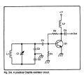
I stumbled upon Oscillators simplified book and I doubt some of it's schematics, for instance:
1794461644930.png

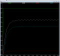
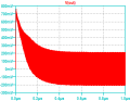
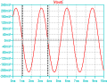
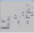
How is the energy in the LC tank circuit regenerated? I have even attempted to simulate it but no luck:
1794461737970.png

1794461747688.png

Green is output, white is base, blue is emitter resistor. Note I have added the emitter myself as the book circuit didn't even have it.
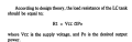
Beside that I noticed this book is slopy on formulas for instance:
1794461844803.png

Should rather be Vcc^2/2PO
 

LvW

Joined Jun 13, 2013
2,062
Each oscillator needs a loop gain somewhat larger than +1.
This means: Positive signal feedback for the desired frequency only.
The shown circuit cannot oscillate.
There must be a 3rd-order lowpass (R-C-L-C)between collector and base.
Tne node between C2 andf L2 must be connected to the base node
You should consult another book for the correct circuit.
 
Last edited:

MisterBill2

Joined Jan 23, 2018
28,550
The arrangement of that circuit is going to be rather more sensitive to the effects of changes in capacitance to all of the surroundings. So while it could oscillate, that version will be more sensitive to extrnal effects.
The feedback would be from the emitter resistor, probably not enough.
 
Last edited:

panic mode

Joined Oct 10, 2011
5,446
How is the energy in the LC tank circuit regenerated?
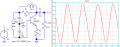
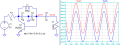
your instinct is correct... that is not a proper circuit. oscillator is an amplifier (with input and output), and with frequency sensitive impedance in the feedback. so that C4 in the book should connect to collector of Q1, not base.
and the other side of LC should connect to base. here is the entire thing in detail:

 
Last edited:
Yeah, your instinct is right — as drawn there's no feedback path back to the base, so the tank just rings down and dies, which is exactly what your sim shows. In a real Colpitts the cap divider taps part of the tank voltage back to the emitter so the loop gain gets over 1 and tops up the losses each cycle. Even with the topology fixed, if the divider ratio is too small or the emitter resistor isn't bypassed, it still won't start — and in sim you usually need a little kick, like an initial condition, since a perfect sim has no noise to get it going.
 

kiroma

Joined Apr 30, 2014
325
Yeah, your instinct is right — as drawn there's no feedback path back to the base, so the tank just rings down and dies, which is exactly what your sim shows. In a real Colpitts the cap divider taps part of the tank voltage back to the emitter so the loop gain gets over 1 and tops up the losses each cycle. Even with the topology fixed, if the divider ratio is too small or the emitter resistor isn't bypassed, it still won't start — and in sim you usually need a little kick, like an initial condition, since a perfect sim has no noise to get it going.
LLMs should be banned here when impersonating a member.
 

kiroma

Joined Apr 30, 2014
325
????? "LLMs " ???
I am not familiar with that term.
Large Language Models, ie. AIs.
Look at the characteristic " — " which is long. You don't have this at the keyboard, only AI does that.
Also, look how well made is his answer, it's all making sense from the very first word, no analogies, no human behavior, very summarized in few lines. It seems like a very knowledgeable guy in the topic, but it's just the perfectness of AI spitting a commentary out.

Also, a new guy in the forum with 14 answers and 8 likes. That's more than 50% in likes, which, for a new guy, it's not common. Very suspect.
 

WBahn

Joined Mar 31, 2012
33,340
MOD NOTE: @MisterBill2, @kiroma: If you want to discuss LLMs, then please start your own thread for that purpose. More than half of the posts are about a completely unrelated topic, so let's refocus the discussion on the TS's topic.
 
Top