Diy Mood lamp

Audioguru

Joined Dec 20, 2007
11,248
The outputs on the PIC are modulated with Pulse-Width-Modulation pulses so you can't measure a DC voltage with a multimeter.
The PIC can drive a base resistor value nearly as low as 100 ohms (25mA) and its output high (the top of each pulse) will be about +3.5V.

I think your breadboard is full of intermittent contacts. Solder an IC socket to stripboard or something solid.

The moderator that "talks back to me" and argues with me is "an engineer with 30+ years experience". But he doesn't know much about electronics.
 

Thread Starter

mentaaal

Joined Oct 17, 2005
451
The outputs on the PIC are modulated with Pulse-Width-Modulation pulses so you can't measure a DC voltage with a multimeter.
The PIC can drive a base resistor value nearly as low as 100 ohms (25mA) and its output high (the top of each pulse) will be about +3.5V.

I think your breadboard is full of intermittent contacts. Solder an IC socket to stripboard or something solid.

The moderator that "talks back to me" and argues with me is "an engineer with 30+ years experience". But he doesn't know much about electronics.
yeah i know i am fully aware that it uses pwm. I used the multimeter on ac voltage and i am also aware that the readout will not be accurate for the same reasons. But what is confusing me is that the output voltage drops so much when i connect the output to something. Why should the voltage change at all? No i am pretty sure that the breadboard is fine because its pretty much new and i have barely used it, although your right it does seem like the most likely candidate for the problems i am experiencing. As said earlier, i put the pic in properly without the use of a pin recepticle so it is now solidly into the breadboard and tapping it does nothing, the leds are only slightly on, like just barely, and i have noticed that again, when i put my finger to one of the base resistors, most prominently the green one, the led die gets much brighter and is visible. Again strange things happening here! I think that i will try and check all patch wires for continuity, maybe one of the cables are broken inside (i am using bell wire as its the only stuff i could find on maplin - tends to break fairly easily although its to be expected as its single core) let you know when i do this what the results are
 

hgmjr

Joined Jan 28, 2005
9,027
Is it possible that the placement of the finger is adding enough additional capacitance to distort the squarewave drive signal being applied to the transistor's base by the PIC and thus changing the PWM duty-cycle in the direction that turns the transistor on for a greater portion of the squarewave? This would explain the increase in the LED's brightness.

By the way, I am in complete accord with beenthere's and audioguru's advocacy of a base resistor between the PIC output and the base of the LED drive transistor. I am baffled by the gentleman's insistance from the other forum that the use of a base current limiting resistor is unnecessary.

hgmjr
 

Thread Starter

mentaaal

Joined Oct 17, 2005
451
Ok i tried re-wiring the schematic, even on a different area of my breadboard. All of the components are securely in place and the same things still happens. I tried increasing the resistance to see if cumesoftware's suggestion was correct. I tried 3 kohm and even 11 kohm and the same thing. The led is barely on and when i touch the base resistors they light up nicely albeit not in the correct fashion, the led just lights up it doesnt fade its just the static colours. Grrrrrrrrr
 

Audioguru

Joined Dec 20, 2007
11,248
the led just lights up it doesnt fade its just the static colours. Grrrrrrrrr
Nobody has explained exactly what the colours are supposed to do. I think the program is supposed to fade and brighten the colours slowly.

6 years ago I made my mood LED lamps with slowly ramping opamp triangle-wave generators. The frequencies of the red, green and blue oscillators are slightly different so they add and project millions of slowly changing colours and brightnesses on the ceiling.
 

Thread Starter

mentaaal

Joined Oct 17, 2005
451
I didn't bother to explain this as this information is contained in the project which i linked to in my first post on this project thread. The pic outputs pwm signals which vary amount of power going to the different colours in the RGB led. By varying its duty cycle (at least i think that is what is occurring here) the perceived intensity of each colour can be varied and thus form the different colours that are supposed to be seen.

There is a 4 bit dip switch in the schematic and this toggles options like changing the colours in different ways or getting them to change dramatically instead of fading although i cant remember what does what i just care about getting the thing to work on a fundamental level!
 

hgmjr

Joined Jan 28, 2005
9,027
Would it be possible for you to take a picture of your bread board and post it here?

With a picture we may be able to spot something amiss.

hgmjr
 

Thread Starter

mentaaal

Joined Oct 17, 2005
451
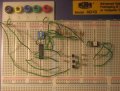
Okidoki here is a picture of my schematic

I forgot to stick the one base resistor back into the bottom transistor but its of little consequence.the resistors feedint into the rgb led are ok as the led lights up just fine when i bridge the led resistor to ground. the loads of resistors on the top are because i didnt have 10k resisors so i have 4 pairs of 20kohms resistors in parallel pairs feeding the dip switches
 

Attachments

hgmjr

Joined Jan 28, 2005
9,027
Hey wait a minute.

It looks like the opposite side of your dip switch is not grounded. Am I missing something there?

That means your 4 dip switch pins are always going to be high no matter what setting the switches are in.

hgmjr
 

hgmjr

Joined Jan 28, 2005
9,027
I am not that well acquainted with programming the PIC but looking at the code it appears that when the dip-switch input corresponding to A6 is high, the program is in "PAUSE" mode.

hgmjr
 

Thread Starter

mentaaal

Joined Oct 17, 2005
451
For god's sake!!! You are of course correct! I quickly grounded the other end of the dips after you pointed out my stupid mistake and tested it with the same result. The first time i wired this circuit it was definitely wired correctly because i noticed that when the pic was partially in, flicking the dips would (either by chance or what i dont know) change the colours but i guess some of the pins in that circumstance weren't making proper contact.

In answer to your other question my confidence is this much: i downloaded the hex code, and stuck it into the pic. I know nothing of programming pics so yeah the only thing i have to go by is that the microchip icd2 program said the pic was programmed successfully. Doh!!!
 
Top