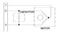
Specifically, the frequency changer needed (Input: ~115V AC, 60 Hz, single phase; Output: 115V AC, 400 Hz., single phase) will be used to power a small 115V AC, single phase, 400 Hertz motor, drawing approximately 0.8 amperes under load. I would like to keep the frequency changer simple, small, and lightweight -- something inexpensive to build if possible. I am considering all ideas previously posted, and I'm hoping to find a schematic or an inexpensive product (~$100) to make this project a success. Please see attached schematic symbols for the fwd/rev motor circuit. Again, I greatly appreciate all help!
The thread title is DIY Frequency changer.... and the op asked for a schematic. The input and output voltages are the same so we just need to rectify the input and use an H bridge output driven by pwm to obtain the 400Hz sine wave. The pwm can be obtained by comparing a 400Hz sine wave with a high frequency triangular wave.
I'm fairly new to this so forgive me if this sounds stupid but would a Wien bridge work at all? I'm having a similar problem where I have 120Vac 60hz going in and needing 115Vac 400hz coming out. Using two internal power supplies in series as the +200 and -200 lines into the wien bridge using PA15 to amplify it.
If you can experiment a bit and are inclined to, there are also some interesting frequency multiplier schemes around. A frequency double scheme using zener diodes to provide pulses from each side of a full-wave two diode rectifier will provide 120 Hz pulses that can nicely drive a transformer-capacitor circuit that resonates at120 Hz. The same scheme could also drive a transformer tuned to 360 Hz, but much less effectively. The drive pulses will need to be narrower for that. The great thing about the scheme is that it needs no external power, and the multiplication is by integer amounts.
(If a Cessna 172 fly up to average 14,000 feet, this circuit being F16 ) I Always mention safety and concern.
It is assumed that working on Viper Pit those doing the modifications would have adequate experience
(High altitude capacitors are sealed in an aluminum can for decreased pressure environment)
Having 2 separate virtual grounds, isolation being another question. The standard for setting guidelines is listed as
MIL-STD-704 (now up to rev. F), ‘Aircraft Electric Power Characteristics’, those who set the requirements
and characteristics of aircraft electric power those designing and using aircraft 400Hz electrical systems.
Short summary of a DIY 400Hz converter. An interesting DIY frequency conversion.
First a 10W proof of concept prototype was built using a TDA2030 audio amplifier.
next a larger version is built outputs up to 100W, Amplified by 2 IRF540s
after that the square wave is converted to sine employing an 18VCT transformer.
Finally the design changes to an op amp oscillator and class D amplifier ...
(If a Cessna 172 fly up to average 14,000 feet, this circuit being F16 ) I Always mention safety and concern.
It is assumed that working on Viper Pit those doing the modifications would have adequate experience
(High altitude capacitors are sealed in an aluminum can for decreased pressure environment)
Having 2 separate virtual grounds, isolation being another question. The standard for setting guidelines is listed as
MIL-STD-704 (now up to rev. F), ‘Aircraft Electric Power Characteristics’, those who set the requirements
and characteristics of aircraft electric power those designing and using aircraft 400Hz electrical systems.
Short summary of a DIY 400Hz converter. An interesting article by distinguished ace on frequency conversion.
First a 10W proof of concept prototype was built using a TDA2030 audio amplifier.
next a larger version is built outputs up to 100W, Amplified by 2 IRF540s
after that the square wave is converted to sine employing an 18VCT transformer.
Finally the design changes to an op amp oscillator and class D amplifier ...
The TS did mention 115v 60Hz, from a wall outlet. I would not anticipate any of those being found in a Cessna aircraft. For a non-aircraft application the requirements can be less demanding.
And if a 400Hz transformer can be found, using a shunt capacitor to resonate it at 400 Hz will enable a class "C" oscillator to deliver a reasonable sine wave with better efficiency.
RE:"" Motors do not like square waves due to the high harmonic content ""
Sure yes, however for to solve this problem was invented the pseudosin generators.
Yet applauding Your eagerness to solder it by own, I have to admit that to buy ir readymade from factoy is absolutely cheepest way to obtain. For 5 kW 380 V motors the adaptive self-learning frequency changer (means You may set what frequency are willing) costs about 150-200 Eur in the shop shelves. Only!
OK, starting back at post #1: The request is for a power source to run a 400Hz motor drawing about 1 amp at 115 volts. That is about 115 watts.
For a short term scheme use a signal generator and an audio amplifier able to deliver at least 100 watts, feeding what used to be called a "filament transformer" that provided 6 volts for tube heaters. Connect the 6 volt winding of the transformer to the 16 ohm output of the amplifier. Connect the signal generator to an amplifier input and monitor the output voltage on the transformer "line side" connection. with the generator set to 400 Hz, increase the output and adjust the amplifier gain. you should be able to get the 115 volts at 400Hz without a lot of distortion.
When I was a kid, we got an aircraft radio that needed 400hz power. The army solved the problem with a motor that ran from power and drove a 400hz generator.
I had a box that had an inverter to produce 120 volts 400Hz. But stuf inside was mechanically broken. A 555 as an oscillator, a TTL flip-flop, two power-tab transistors, and a 12 volt rectifier power supply. Left behind at a swap.
As someone has already suggested, an audio power amplifier with a low voltage transformer reversed, will do the trick.
Be aware that, power transformers rated for 50/60 Hz will become very hot when operated at 400 Hz.
Be aware though, that the core losses for transformers designed for powerline-frequency will be very high(*). But for intermittent operation is fine.
I have actually tested it.
(*) the core losses will be dependent on the steel grade and lamination thickness. YMMV.
If the amplifier had a 141 volts output, like some of the higher power PA amplifiers, then it would be really simple. Or even a 70.7 volt output like a 100 watt PA amp. THOSE are quite common.
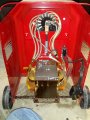
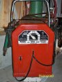
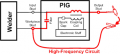
Hi, I'm new I don't know how to start a new thread but this might be a place I can start. I want to build a DIY inveter for adjustable output frequency for TIG welding. (60Hz to up to 400Hz) I have a Lincoln AC 225 ARC Welder machine. It runs on 220 volts. Adjusting the output frequency allows for fine tuning of the welding process. I don't know what information is needed to answer my questions but I'll do my best to provide it if someone can help. There's not much to this machine. On, off and amperage up and down. I also have an Arc Pig arc stabilizer that that allows this machine to weld aluminum. It's basically like a tesla coil and spark plug that keeps restarting the welding arc.
I have no idea where to start with the inverter. I read in one of the comments that someone needed to know what shape of wave. Square wave welders are common. I couldn't tell you what this is.
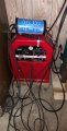
The first two pictures are an AC only Lincoln welder. Then a picture of an AC and DC Lincoln welder, much more powerful and quite a few options.
Based on the picture and the posted circuit it is not possible to explain how the ARC PIG does what it claims to do. Really a good job of telling the truth while not revealing anything.
The first two pictures are an AC only Lincoln welder. Then a picture of an AC and DC Lincoln welder, much more powerful and quite a few options.
Based on the picture and the posted circuit it is not possible to explain how the ARC PIG does what it claims to do. Really a good job of telling the truth while not revealing anything.
Yes I labeled the picture of the AC and DC machine as "not my machine " but my set up will be like that. I'm waiting on connecting parts. Before I can test it.

 Facebook
 Google
 GitHub
 Linkedin