Facebook
 Google
 GitHub
 Linkedin
HELP!!!
I've built this pedal, and I cant identify what's wrong.

If both pre-gain and gain are turned up, a steady, fast ticking noise appears, or a loud high pitched whistle, depends on which one is turned up first, with no signal from the bass coming through. With both these knobs turned down, the signal can be heard, undistorted, quiter than when the circuit is bypassed. The bass signal could be heard with the volume turned down, but the before mentioned issues appear when the volume is up, so i just removed it until i solve the issue.
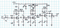
I've built an LTspice simulation to compare voltage values, and these are the main points:

1.voltages before the collectors of Q1 and Q2 are identical in the simulation, 4.228.. , but it's 4.9 and 4.16 in my circuit
2. Voltages before and after the diodes are identical in the simulation, but it's 4.14 on on the side of Q2 and 3.99 on the side of C7.
3. After the 10uf output cap, voltage should be 42uv, but in my circuit, the value started at around 2.4V and is slowly droping, removing the multimeter leads, and then reapplying them, didn't reset the value, turning the power on and off didn't reset the value, it kept dropping, it was around 600mv last time, but when i meassured it now, it randomly jumped up to 1.4V and is now steadily decreasing again. There are no solder bridges or anything, like that. Should voltage even be able to travel through the cap?
These are the main clues to what could be wrong, I really need some guidance on how to figure out what's going on. I've built this circuit twice now, and the problems are identical this time as they were the first time. I'm new to this, so don't be afraid to suggest anything to basic.
I have no idea what to do next, and what to look for. I'm using a 9v battery,but the actual value of my battery is 9.5v
The firs template i used called for different diodes, that's why they're not the same as in the circuitboad diagram.
I've built this pedal, and I cant identify what's wrong.
If both pre-gain and gain are turned up, a steady, fast ticking noise appears, or a loud high pitched whistle, depends on which one is turned up first, with no signal from the bass coming through. With both these knobs turned down, the signal can be heard, undistorted, quiter than when the circuit is bypassed. The bass signal could be heard with the volume turned down, but the before mentioned issues appear when the volume is up, so i just removed it until i solve the issue.
I've built an LTspice simulation to compare voltage values, and these are the main points:
1.voltages before the collectors of Q1 and Q2 are identical in the simulation, 4.228.. , but it's 4.9 and 4.16 in my circuit
2. Voltages before and after the diodes are identical in the simulation, but it's 4.14 on on the side of Q2 and 3.99 on the side of C7.
3. After the 10uf output cap, voltage should be 42uv, but in my circuit, the value started at around 2.4V and is slowly droping, removing the multimeter leads, and then reapplying them, didn't reset the value, turning the power on and off didn't reset the value, it kept dropping, it was around 600mv last time, but when i meassured it now, it randomly jumped up to 1.4V and is now steadily decreasing again. There are no solder bridges or anything, like that. Should voltage even be able to travel through the cap?
These are the main clues to what could be wrong, I really need some guidance on how to figure out what's going on. I've built this circuit twice now, and the problems are identical this time as they were the first time. I'm new to this, so don't be afraid to suggest anything to basic.
I have no idea what to do next, and what to look for. I'm using a 9v battery,but the actual value of my battery is 9.5v
The firs template i used called for different diodes, that's why they're not the same as in the circuitboad diagram.
Attachments
-
4.7 KB Views: 5