 Facebook
 Google
 GitHub
 Linkedin
Hello,
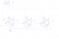
I had designed an SR latch, and then built a D Flip-Flop out of it, which works perfectly fine, later I found out about edge triggering the circuit, and how to do that, but now I have the following problem: It won't loop back to the first one, (see below how it should work)
1 100
2 010
3 001
and then back to line one (which won't work in the actual circuit appearantly)
The loop works just fine in Logisim, but I can't get it to work in Circuit Wizard or NI Multisim.
If it doesn't work in a simulation, I don't think it would work when I make
Can anyone help me fix this problem?
Many Many Many thanks")
I had designed an SR latch, and then built a D Flip-Flop out of it, which works perfectly fine, later I found out about edge triggering the circuit, and how to do that, but now I have the following problem: It won't loop back to the first one, (see below how it should work)
1 100
2 010
3 001
and then back to line one (which won't work in the actual circuit appearantly)
The loop works just fine in Logisim, but I can't get it to work in Circuit Wizard or NI Multisim.
If it doesn't work in a simulation, I don't think it would work when I make
Can anyone help me fix this problem?
Many Many Many thanks
Attachments
-
 62.8 KB Views: 35
 -
 5.8 KB Views: 30


