
 Facebook
 Google
 GitHub
 Linkedin
I'm looking through my notes and came across this example. I can't seem to grasp it.
The question is:
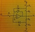
Design a limiter with Av = -10 in the +- 5v output range and Av = -1 outside that range.
The attached picture shows the circuit that was drawn with the question.
Thus far I have made the following assumptions:
- The diodes will always be in opposite bias. One will be an open circuit while the other will be a short circuit.
- The op-amp is used to get the Av = -10 gain thus \(\frac{R_{f}}{R_{1}} = -10\)
I realize that R2 thru R5 are used to scale down the gain back to -1 when the output voltage falls outside the given range.
So how does one go about finding the R2-R5 values and some explanation as to how this circuit operates would be great !
Thanks!
The question is:
Design a limiter with Av = -10 in the +- 5v output range and Av = -1 outside that range.
The attached picture shows the circuit that was drawn with the question.
Thus far I have made the following assumptions:
- The diodes will always be in opposite bias. One will be an open circuit while the other will be a short circuit.
- The op-amp is used to get the Av = -10 gain thus \(\frac{R_{f}}{R_{1}} = -10\)
I realize that R2 thru R5 are used to scale down the gain back to -1 when the output voltage falls outside the given range.
So how does one go about finding the R2-R5 values and some explanation as to how this circuit operates would be great !
Thanks!
Attachments
-
 293.1 KB Views: 34






