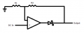
Diode at Op Amp Output

Thread Starter

jwilk13

Joined Jun 15, 2011
228
I recently came across a simple schematic that I had a question about, so I thought I'd post it here. It's a simple non-inverting amplifier configuration, but with a Schottky diode at the output inside the feedback loop. The only thing I can think of is that it's used to protect the op-amp's output or possibly drop the voltage to a specific value. But if it were simply there to protect the output, couldn't it be placed outside the feedback loop?

Any thoughts?
 

Attachments

#12

Joined Nov 30, 2010
18,224
The diode is inside the loop so that the output voltage after the diode's voltage drop is proper for the equasion for gain: Vo = Vin x (1+ (R2/R1)) You could imagine the diode to be inside the op-amp with exactly the same result.

The diode forces a lack of negative voltage output from the amplifer, no matter what the input is, but it does not interfere with the gain equasion.
 

Thread Starter

jwilk13

Joined Jun 15, 2011
228
Both very interesting!

How about if the supply rails for the op-amp are +Vs and ground? The op-amp wouldn't be able to output a negative voltage anyways, correct?

As far as not interfering with the gain, that makes total sense. If you change the connection and put the diode outside the feedback, the output voltage drops due to the drop of the diode.
 

#12

Joined Nov 30, 2010
18,224
If you're going to go messing with the power rail voltages you're going to have to give me a drawing. (My imagination level is only about a 6 today.)

Let's change to the word, "current". No matter how you mess with the supply voltages, no electrons will come out of the op-amp and go through the diode.
 

Thread Starter

jwilk13

Joined Jun 15, 2011
228
If you're going to go messing with the power rail voltages you're going to have to give me a drawing. (My imagination level is only about a 6 today.)

Let's change to the word, "current". No matter how you mess with the supply voltages, no electrons will come out of the op-amp and go through the diode.
I was just thinking out loud (at least about as loud as my typing is). This makes sense.

And Bill, question 5 isn't similar to what I'm talking about. Maybe I'm missing something?
 

WBahn

Joined Mar 31, 2012
33,327
Is it?

When the input is negative, the output is resistively tied to ground. That's not what I usually think of when I think of a half-wave rectifier. But it's certainly close.
 

crutschow

Joined Mar 14, 2008
38,936
Is it?

When the input is negative, the output is resistively tied to ground. That's not what I usually think of when I think of a half-wave rectifier. But it's certainly close.
You left us hanging. ;) So what do you think of when you think of a half-wave rectifier? For a negative input, the output is zero volts, which is what a half-wave rectifier would provide. Where would you tie the output for a negative input voltage if not ground?

Understand this is for signal rectification only, not for power rectification.
 
Top