Dim Bulb Tester with Power Meter Design Review

Thread Starter

redocoder

Joined May 7, 2023
6
Hello,
This is my first post on the forum and I'm seeking some guidance.

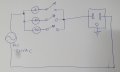
Would anyone mind looking over my schematic for a dim bulb tester and giving me feedback?

The input is coming from an isolated AC lab power supply. Relays are actually DPDT 1NO1NC and the bulbs are E27 fixtures not LEDs as shown in the schematic.

I am building this in a din rail distribution box with a power meter that has over/under voltage/current protections and wireless monitoring/control.

I'm wondering if I should use the terminal blocks like I have it laid out or just run everything in series?

Thanks,
redocoder

schematic.PNG
 

MisterBill2

Joined Jan 23, 2018
27,181
OK, I sort of see, sort of, and it does appear that the sections are sort of in series. But the drawing is really rather difficult to follow, and all of the long lines between parts do not add any useful information.
The common NEMA symbol for a light is indeed a circle, but the four line segments are outside the symbol, often at the 45 degree angle, but not quite touching the circle. And if it is a pilot light, there is a letter inside designating the color.
Very often, circuit schematic drawings are drawn ladder style, with the power supply lines being vertical. The benefit is that the drawings mostly read like text, from left to right and top toward bottom.
 

Thread Starter

redocoder

Joined May 7, 2023
6
OK, I sort of see, sort of, and it does appear that the sections are sort of in series. But the drawing is really rather difficult to follow, and all of the long lines between parts do not add any useful information.
The common NEMA symbol for a light is indeed a circle, but the four line segments are outside the symbol, often at the 45 degree angle, but not quite touching the circle. And if it is a pilot light, there is a letter inside designating the color.
Very often, circuit schematic drawings are drawn ladder style, with the power supply lines being vertical. The benefit is that the drawings mostly read like text, from left to right and top toward bottom.
I really appreciate the input, this is my first time doing a schematic or a project like this, I'm kinda flying blind.
Here is an update. Many thanks, I will do some more research on schematic formatting per your suggestion.

schematic.PNG
 

Sensacell

Joined Jun 19, 2012
3,768
The schematic is still very difficult to read- too many lines crossing.
The concept of the "terminal strip" as a component makes the drawing messy.
A terminal strip is a wiring solution, not a circuit element that needs to be in a schematic.
All the lines that connect to this terminal strip should be replaced with one simple clean line.

Focus on communicating the design intent in the cleanest, simplest manner, not how you wire this in practice.
Power and signals generally flow from left-to-right, top-to-bottom.


Ever look at the wiring diagram for a motorcycle? These are drawn from a wiring-centric point of view, not with the goal of understanding how it works, but where the wires are supposed to go.
This kind of diagram makes understanding what is going on extremely difficult.
 
Last edited:

Thread Starter

redocoder

Joined May 7, 2023
6
The schematic is still very difficult to read- too many lines crossing.
The concept of the "terminal strip" as a component makes the drawing messy.
A terminal strip is a wiring solution, not a circuit element that needs to be in a schematic.
All the lines that connect to this terminal strip should be replaced with one simple clean line.

Focus on communicating the design intent in the cleanest, simplest manner, not how you wire this in practice.
Power and signals generally flow from left-to-right, top-to-bottom.


Ever look at the wiring diagram for a motorcycle? These are drawn from a wiring-centric point of view, not with the goal of understanding how it works, but where the wires are supposed to go.
This kind of diagram makes understanding what is going on extremely difficult.
I've worked on the schematic a bit and simplified some things. Hope this looks better.
schematic2.PNG
 

MisterBill2

Joined Jan 23, 2018
27,181
OK, the circuit has improved at each iteration.
Now I still have a question which is "What is it supposed to do??"
I see a power input connector on a cord , and then one, two, or three lights in series, and then a "power meter", all feeding an electrical outlet.

I can make a guess that it is a system to evaluate the power draw of "devices" connected to the electrical outlet. And I am again guessing that the light bulbs are for limiting the current to protect the power meter. But those are all only guesses based on what I think the circuit does.
 

Thread Starter

redocoder

Joined May 7, 2023
6
OK, the circuit has improved at each iteration.
Now I still have a question which is "What is it supposed to do??"
I see a power input connector on a cord , and then one, two, or three lights in series, and then a "power meter", all feeding an electrical outlet.

I can make a guess that it is a system to evaluate the power draw of "devices" connected to the electrical outlet. And I am again guessing that the light bulbs are for limiting the current to protect the power meter. But those are all only guesses based on what I think the circuit does.
Your guesses are correct, this is intended to be a dim bulb current limiting device to protect vintage electronics that I am testing and repairing. The power meter is an extra bit I added for monitoring and protection with its overcurrent protection circuit. This is also an exercise for me to familiarize myself with circuit design software and schematics.

Does everything look in order to you, any recommendations or problems to point out?

I just want to add that I highly value and appreciate everyones input on my project and I’m honored to join such a knowledgeable community.
 

MisterBill2

Joined Jan 23, 2018
27,181
It looks like the lamps are bypassed in sequence to avoid excess currents. Very effective and quite reliable, but not anything new. In the hands of an operator who understands what is happening it is a great system that is very reliable.

The circuit in post #12 would be effectively similar to the original post if the three lamps were in series and the switches were each to bypass the one lamp they were across. The use of the relays to effect the bypassing is probably to avoid excessive current thru the switches. it does make the circuit analysis more complex as drawn.
 
Last edited:
Top