Differential probe in simulation model

Thread Starter

Olle_Sch

Joined Sep 14, 2018
9
Hello,

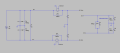
I´m going to build up a simulation model in LT Spice of a circuit and compare the results with a real measurement, performed with a voltage differential probe. To be able to get that comparison as accurate as possible, I need to introduce probe in the simulation model, but I don't really know how to build up electrical characteristics of the probe.

Many Thanks!
 

Bordodynov

Joined May 20, 2015
3,180
You can add (to simulate the effect) the necessary resistor and a parallel capacitor (for example, 1MΩ and 50pF). The advantage of own probes - infinite resistance and zero capacitance allows you to see what happens when you do not insert probes (ie see real work).
With a probe and without a probe, these are two different schemes.
 

Thread Starter

Olle_Sch

Joined Sep 14, 2018
9
Exactly. But in this case I want to insert probes in the model, but I don't know how to create a model of the probes.
 

ericgibbs

Joined Jan 29, 2010
18,849
hi Olle,
Are you asking how to measure/plot a differential voltage between two Nodes on your circuit.
If yes, place the cursor on Node 1, keeping the mouse key down, move the cursor across to Node 2 and release the key.
You must have run the Sim first, before attempting a measurement.
E
 

Thread Starter

Olle_Sch

Joined Sep 14, 2018
9
hi Olle,
Are you asking how to measure/plot a differential voltage between two Nodes on your circuit.
If yes, place the cursor on Node 1, keeping the mouse key down, move the cursor across to Node 2 and release the key.
You must have run the Sim first, before attempting a measurement.
E
I´m fully aware how to make a differential measurement in LT Spice. But I want to introduce the effect of a differential voltage probe from Fluke (or similar) into my simulation model.
 

Bordodynov

Joined May 20, 2015
3,180
If you just want to attach a differential probe between two test points in the circuit and automatically get the output in the plot window, then this is not possible. In some, other programs, this can be done, but not in LTspice. In this case, I put the capacitor on and set the Rpar if necessary.
 

Thread Starter

Olle_Sch

Joined Sep 14, 2018
9
Just to put a resistor en parallel with a capacitance was my first thought too. Bu then I got confused by this wording from Fluke, concerning their differential probe DP120
"Input impedance between each input to shielding BNC is 5 MΩ in parallel with 6 pF. Input impedance between the inputs is 10 MΩ with a capacitance of 5 pF"

I have tried to simulate with and without this "input to shield" circuit, and the existence of that part is affecting the simulation results.
 

Thread Starter

Olle_Sch

Joined Sep 14, 2018
9
I have made a simplified version of the system I want to evalute and added a differential probe according to said Fluke. Does it looks resonable? I´m planning to evaluate DC_Out+ vs DC_Out- as well as each DC_Out vs ground.

A colleague to me passed by and told my that is could be multimeters, rather than differential probles that will be used. I find it even more difficult to build a simulation model of such voltmeter, becasue I couldn't even find any info about the electrical characteristics.


upload_2018-9-20_10-19-51.png
 

Attachments

kubeek

Joined Sep 20, 2005
5,795
With a DC circuit and ideal voltage source, what do you expect that could possibly be changed with that probe?
Anyway, multimeters have typically 10meg internal resistance, and some unknown capacitance, as they are never used in situations where said capacitance would matter the least bit.
 

Thread Starter

Olle_Sch

Joined Sep 14, 2018
9
With a DC circuit and ideal voltage source, what do you expect that could possibly be changed with that probe?.
Since the circuit remain open until the measuring equipment is connected, the results, obviously, become very different depending on how the model of the measuring equipment looks like.
 

kubeek

Joined Sep 20, 2005
5,795
I don´t undestand what you mean by that. What part of the circuit remains open? What is disconnected?
And why does it matter? The 500V source has 0 ohms internal resistance. Nothing you put across that supply will change the fact that it produces 500V, and if the switch on resistance is also close to 0 the probe will measure 500V across the rails.
 

Thread Starter

Olle_Sch

Joined Sep 14, 2018
9
I don´t undestand what you mean by that. What part of the circuit remains open? What is disconnected?
And why does it matter? The 500V source has 0 ohms internal resistance. Nothing you put across that supply will change the fact that it produces 500V, and if the switch on resistance is also close to 0 the probe will measure 500V across the rails.
When the two contactors open up, through the CON-Ctrl, there is no "real" closed loop outside the contactors. When only using the build-in probes of LT Spice which, as I assume, has infinite resistance, LTSpice will report 500V between DC_Out+ and DC_Out-. But when measuring in such system, in reality, the readout from the measuring equipment (differential probe, multimeter, etc) wil never be 500V.

In that perspective, the electrical characteristics of probe is important to know.
 
Top