Facebook
 Google
 GitHub
 Linkedin
Good morning everyone,
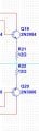
I created and simulated a current buffer circuit made up of pairs of BD139 and BD140. This circuit does not increase the voltage but adds current. I have noticed that by replacing these transistors with the newer "G" versions ie BD139G and BD140G I have an increase in THD distortion from 0.15% to 2%. To reduce this distortion percentage I have to modify the resistances on the collector. Therefore it would seem that the replacement of these transistors with the "G" versions is not direct but requires the modifications of the above. I enclose the spice data used in the various transistors as they are inserted in the simulator.
I created and simulated a current buffer circuit made up of pairs of BD139 and BD140. This circuit does not increase the voltage but adds current. I have noticed that by replacing these transistors with the newer "G" versions ie BD139G and BD140G I have an increase in THD distortion from 0.15% to 2%. To reduce this distortion percentage I have to modify the resistances on the collector. Therefore it would seem that the replacement of these transistors with the "G" versions is not direct but requires the modifications of the above. I enclose the spice data used in the various transistors as they are inserted in the simulator.
BD139
+ (
+ IS = 4.815E-14
+ NF = 0.9897
+ ISE = 1.389E-14
+ NE = 1.6
+ BF = 124.2
+ IKF = 1.6
+ VAF = 222
+ NR = 0.9895
+ ISC = 1.295E-13
+ NC = 1.183
+ BR = 13.26
+ IKR = 0.29
+ VAR = 81.4
+ RB = 0.5
+ IRB = 1E-06
+ RBM = 0.5
+ RE = 0.165
+ RC = 0.096
+ XTB = 0
+ EG = 1.11
+ XTI = 3
+ CJE = 1.243E-10
+ VJE = 0.7313
+ MJE = 0.3476
+ TF = 6.478E-10
+ XTF = 29
+ VTF = 2.648
+ ITF = 3.35
+ PTF = 0
+ CJC = 3.04E-11
+ VJC = 0.5642
+ MJC = 0.4371
+ TR = 1E-32
+ CJS = 0
+ VJS = 0.75
+ MJS = 0.333
+ FC = 0.9359 )
BD139G
+IS=1e-09 BF=222.664 NF=0.85 VAF=36.4079
+IKF=0.166126 ISE=5.03418e-09 NE=1.45313 BR=1.35467
+NR=1.33751 VAR=142.931 IKR=1.66126 ISC=5.02557e-09
+NC=3.10227 RB=26.9143 IRB=0.1 RBM=0.1
+RE=0.000472454 RC=1.04109 XTB=0.727762 XTI=1.04311
+EG=1.05 CJE=1e-11 VJE=0.75 MJE=0.33
+TF=1e-09 XTF=1 VTF=10 ITF=0.01
+CJC=1e-11 VJC=0.75 MJC=0.33 XCJC=0.9
+FC=0.5 CJS=0 VJS=0.75 MJS=0.5
+TR=1e-07 PTF=0 KF=0 AF=1
BD140
+ (
+ IS=7.401E-14
+ NF=0.9938
+ ISE=4.104E-16
+ NE=1.054
+ BF=336.5
+ IKF=0.1689
+ VAF=22.47
+ NR=0.9913
+ ISC=1.290E-14
+ NC=1.100
+ BR=13.91
+ IKR=9.888E-2
+ VAR=30.00
+ RB=0.500
+ IRB=1E-06
+ RBM=0.500
+ RE=0.208
+ RC=5.526E-02
+ XTB=0
+ EG=1.11
+ XTI=3
+ CJE=1.066E-10
+ VJE=0.6900
+ MJE=0.3676
+ TF=2.578E-10
+ XTF=13.56
+ VTF=2.366
+ ITF=1.3040
+ PTF=0
+ CJC=5.234E-11
+ VJC=0.6431
+ MJC=0.4436
+ XCJC=0.440
+ TR=1E-25
+ CJS=0
+ VJS=0.75
+ MJS=0.333
+ FC=0.990 )
So the question is: If in a real circuit I replace the 139/140 burned with the "G" versions, are these directly replaceable without other modifications or is there really this difference that also requires the modification of the collector resistors or other ?. Do you have experiences on this? ThanksBD140G
+IS=1e-09 BF=650.842 NF=0.85 VAF=10
+IKF=0.0950125 ISE=1e-08 NE=1.54571 BR=56.177
+NR=1.5 VAR=2.11267 IKR=0.950125 ISC=1e-08
+NC=3.58527 RB=41.7566 IRB=0.1 RBM=0.108893
+RE=0.000347052 RC=1.32566 XTB=19.5239 XTI=1
+EG=1.05 CJE=1e-11 VJE=0.75 MJE=0.33
+TF=1e-09 XTF=1 VTF=10 ITF=0.01
+CJC=1e-11 VJC=0.75 MJC=0.33 XCJC=0.9
+FC=0.5 CJS=0 VJS=0.75 MJS=0.5
+TR=1e-07 PTF=0 KF=0 AF=1