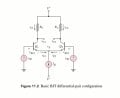
Diffential amplifier concept

Thread Starter

Photon3

Joined Oct 3, 2026
1
This image is taken from the book Electronic circuits by Donald A. Neamen.

I am facing problem in understanding it's concept so I have new questions here.

1.Will current flow in the circuit from positive Vcc to negative Vcc even when the inputs Vb1 and Vb2 are open circuits?


2.There is a constant current source at the tail of this circuit and as far as I know is that an independent current source provide the constant current in the circuit regardless of the other components in the circuit so will the current remain constant in this circuit no matters what the values of positive Vcc, negative Vcc, inputs Vb1 and Vb1?

3.If input Vb1 is greater than Vb2 then bjt Q1 will draw more current and Q2 will draw less current? Is this because the constant current coming from the constant current source will go more towards Q1 because it's base current is now more than the bjt Q2 but the overall current in the circuit will remain constant?
 

Attachments

BobTPH

Joined Jun 5, 2013
11,662
Before answering your questions, please realize this is mot a practical circuit, it is a skeleton, using biassing voltage sources and current siurces where tgere would be actual components in a teal circuit.

1. Yes, there are biasing voltages on the based which turn the transistors partially on.

2. No, there is no such thing, it is a theoretical concept. A practical circuit will have limitations.

3. Yes, that is how a differential amp works, the two transistors split the current according to the difference between the two inputs.
 

WBahn

Joined Mar 31, 2012
33,281
This image is taken from the book Electronic circuits by Donald A. Neamen.

I am facing problem in understanding it's concept so I have new questions here.

1.Will current flow in the circuit from positive Vcc to negative Vcc even when the inputs Vb1 and Vb2 are open circuits?
No, unless there are bias circuits that bias the bases slightly, which there may or may not be. If there aren't then both outputs go to Vcc and the differential output is still zero, as you would expect.

2.There is a constant current source at the tail of this circuit and as far as I know is that an independent current source provide the constant current in the circuit regardless of the other components in the circuit so will the current remain constant in this circuit no matters what the values of positive Vcc, negative Vcc, inputs Vb1 and Vb1?
Only in theory. In theory, a constant current source that is open circuited will create such a high voltage across it's terminals that the needed current will arc across empty space. But, in reality, that's not going to happen since there is a maximum voltage that the current source can deliver.

3.If input Vb1 is greater than Vb2 then bjt Q1 will draw more current and Q2 will draw less current? Is this because the constant current coming from the constant current source will go more towards Q1 because it's base current is now more than the bjt Q2 but the overall current in the circuit will remain constant?
Yes. The difference between Vb1 and Vb2 causes an imbalance between the two transistors resulting in the current in one going up by a certain amount and the current in the other going down by, ideally, the same amount. But for that difference to be linear with respect to the difference between Vb1 and Vb2, the input difference must be less than about the thermal voltage.
 

MisterBill2

Joined Jan 23, 2018
28,454
REAL transistors exhibit some amount of leakage current, which may be less than average REAL meters would register. Some data sheets list that current, many do not list it.
The amount of leakage current is small enough to not matter in many applications, and thus it is sometimes ignored.
Just because it may be too small to easily measure does not mean it does not exist.
 

panic mode

Joined Oct 10, 2011
5,307
1. only the leakage current. usually the current source shown in emitter circuit is in uA range. so leakage current would have to be much smaller for circuit to be useful.
2. constant current source in emitter circuit is not really a constant current source as learned in theory. that is just a model. in reality, that part of the circuit is current limiter. when inputs are open/floating, only leakage current will seep through and this may be orders of magnitude smaller than whatever constant current source is set for. real constant current source would actively increase voltage until set current flows through - regardless of supply voltage V+, V-. obviously, here that is not the case since V+,V- are responsible for all currents in the circuit.
3. that is exactly how it works. the Ib current in BJTs is in base-emitter circuit, so both base and emitter can act as input. Ic current is in collector-emitter circuit so both collector and emitter can act as output. and you know that Ib<<Ic as well as Ie=Ib+Ic so Ie and Ic are nearly the same (in most cases).
 
Last edited:

LvW

Joined Jun 13, 2013
2,038
I think, before discussing specific questions it is necessary to UNDERSTAND the basic function of the circuit.
For this purpose, you should replace the constant current source by a simple (large) ohmic resistor RE.

(1) Set Vb2=0 and realize that the circuit is nothing else than a series connection of an emitter follower (Q1 as a common collector) and a common base amplifier stage Q2.
Hence, The output Vc2 is an amplified version of Vb1.
Note that the existence of the left Rc (at Q1) will not disturb the emitter follower principle of Q1.
Note also that for identical values Rc the output Vc1 is the negative version of Vc2 (Vc1=-Vc2).
This assumes a nearly ideal emitter follower function with unity gain (therefore, we have assumed a large common emitter resistor RE).

(2) Set Vb1=0 and realize that (seen from the right) the series connection of Q2-Q1 resembles the same function (emitter follwer Q2 in series with a common-base amplifier Q1).
Hence, The output Vc1 is an amplified version of Vb2.

(3) If both inputs (Vb1 and Vb2) are existent at the same time we can superimpose both functions and the output signals at Vc1 and Vc2 will be composed of the difference Vc1=f(Vb2-Vb1) as well as Vc2=-Vc1=f(Vb1-Vb2).
Hence, both output signals are an amplied version of the input difference and have the same magnitude, but different sign.

(4) Final note: Because the resistor RE (assumed as very large) must work as a DYNAMIC large resitor only, it is common practice to replace it with a 3rd transitor Q3 having a large dynamic output resistance rc (several tens of kOhms).
Such a stage resembles a pretty good constant current source.
 
Last edited:
Top