Diagnosis of Marshall 8100 Valvestate head problems

Thread Starter

wolf1419

Joined Nov 1, 2008
117
You know,
Semiconductor in circuit testing is not reliable, although if you checking for shorts is OK, but what if you get a reading from both ways in a diode, only experience can tell if they OK, best way is to disconnect one pin, same goes for transistors.

Resistors tend to give abnormal reading in circuits if there are charged caps, u know.

Anyways, meddling with it can give you experience.

I advise to use my method to test your amp, post back and I will guide you through biasing and all.

Rifaa
Good info for sure.....OK, so that's what I expected, but needed to hear it from the pros. There is no actual way to calculate what readings should be expected while in circuit for diodes & transistors, and even some resistors, (without power)unless you take it out of circuit(undo 1 pin) for proper testing.

What I've done so far is good for meddling, as you say, no open resistors, etc...no bulging caps found, power supply has been verified, and eliminating shorts, at the very least....beyond that, it's putting new TR8 & TR10 on board, do some final checks for shorts, etc...... and either it's fixed(if I'm really lucky).......:D, or go through your setup(I only have 1 main fuse), process, and learn biasing, which probably would be a good learning experience anyway......sound like a reasonable plan..?
 
Last edited:

bertus

Joined Apr 5, 2008
23,023
Hello,

About the TR9 measurement.
Take a look at this chapter: http://www.allaboutcircuits.com/vol_3/chpt_4/3.html
Inside the meter there is a currentsource (about 1 mA) and a voltmeter.
As descibed on the given page, you will get several readings.
But when a resistor is parallel to the transistor, you will probably measure the resistor when the voltage is to low.

@ rifaa,
Glad you are joining in.
I am not very experienced with audio equipment.
I am more a "pure" electronics guy with an emphasis on RF.

Greetings,
Bertus
 

Thread Starter

wolf1419

Joined Nov 1, 2008
117
Hello,

About the TR9 measurement.
Take a look at this chapter: http://www.allaboutcircuits.com/vol_3/chpt_4/3.html
Inside the meter there is a currentsource (about 1 mA) and a voltmeter.
As descibed on the given page, you will get several readings.
But when a resistor is parallel to the transistor, you will probably measure the resistor when the voltage is to low.

@ rifaa,
Glad you are joining in.
I am not very experienced with audio equipment.
I am more a "pure" electronics guy with an emphasis on RF.

Greetings,
Bertus
Thanks to all my new, positive, and helpful friends from around the world....I'm not having as much luck with help here in the USA. Our country seems to be on a collision course as far as greed, corruption, lack of manufacturing, services, etc........I personally thank my new friends from around the world......this is GREAT!!!

TR8 & TR10 are now onboard........next will be any other measurements, testing, checking prior to hitting the on switch...a little scared about hooking a speaker to this, but it probably should have a load(8ohm), or it may blow because of that, or is that more true with tube amplifiers.............?
 
Last edited:

bertus

Joined Apr 5, 2008
23,023
Hello Ron,

When you use Rifaa's method (with the resistors in the place of the fuses), things will be rather safe.
It is good to have a 8 Ohm resistor as load, you can measure the voltage accross it as described by Rifaa.

Greetings,
Bertus
 

Thread Starter

wolf1419

Joined Nov 1, 2008
117
1) When I am able to get the 22ohm and 8ohm resisters, I am still wondering if I'll just be inserting the 22ohm in place of the 1 and only fused line I have, or am I trying to break some circuits to install these.....if so where in the schematic would be the best location to break the circuits....?
2) The input grounding would just be a jumper from the +(pin) to sleeve(gnd)....basically a short circuit at input....is this correct....?
3) The 8 ohm resistor will be in place of the missing speaker....correct..?
 
Last edited:

bertus

Joined Apr 5, 2008
23,023
Hello Ron,

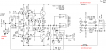
The 22 Ohm resistors should be placed between the + VE and rectifier bridge (break the connection for it).
And the - VE and the other rectifier connection (also break the connection for it).
(There are no low voltage fuses in the schematic).

The 8 Orm resistor ( enough powerfull ) can be placed in stead of the speaker.

To "short" the input make a short accross R26 ( the - input IC8B ).

Follow the instructions of Rifaa for measurement.

Greetings,
Bertus
 

Thread Starter

wolf1419

Joined Nov 1, 2008
117
I can only get access to 1 ohm/10w, 10ohm/10w, 50ohm/10w, 100ohm/10w(already have these for draining caps) and an 8ohm(non-inductive)/20w resistor at my local store....
Which ones will work, or will I have to try to order the correct values..
OR:
(dual 10ohms in series = 20ohms is another option (2)x2 legs..just more $)(4 components)
(dual 10ohms + dual 1ohm in series = 22ohms (4)x2 legs...even more$$$)(8 components)
 
Last edited:

bertus

Joined Apr 5, 2008
23,023
Hello Ron,

I would take the 10 Ohms / 10 Watt for the powerlines (2 times for +VE and -VE).
The 8 Ohms 20 watt will be enough for the test. (you will not drive it hard in the test).

Greetings,
Bertus
 

Thread Starter

wolf1419

Joined Nov 1, 2008
117
Hello Ron,

I would take the 10 Ohms / 10 Watt for the powerlines (2 times for +VE and -VE).
The 8 Ohms 20 watt will be enough for the test. (you will not drive it hard in the test).

Greetings,
Bertus
Is that (1)10ohm for +V, (1)10ohm for -V, or did you mean I need to double up(series) to 20ohm on each side...I wasn't clear on the intent, but assume it's 20ohm.....just want to confirm if it's necessary, and maybe another WHY, if you have that answer to WHY 22ohm was chosen in the first place.
 
Last edited:

bertus

Joined Apr 5, 2008
23,023
Hello Ron,

No, there is no need to double it up.
It is only to reduce the current to a safe value.

Greetings,
Bertus
 

Thread Starter

wolf1419

Joined Nov 1, 2008
117
Hello Ron,

No, there is no need to double it up.
It is only to reduce the current to a safe value.

Greetings,
Bertus
So 22ohms is somewhat random, and 10ohms is sufficient resistance to get this job done, assuming I don't have some massive current develop somewhere in this power stage....in which case 50ohms would be even safer...is that an improper conclusion..? Part of the learning curve only to question all angles...
 
Last edited:

bertus

Joined Apr 5, 2008
23,023
Hello Ron,

In a way yes.

With the 50 Ohms, it could be the amplifier is giving trouble due to the voltage drop.

It is to test if the circuit for the quisent current is working.
There will be max 0.1 A with no input signal.
This will lead to a voltage LESS than 1 volts accross the resistors.
If the voltage is more and the resistors get hot, there is someting wrong.

There is more in these articles:
http://sound.westhost.com/troubleshooting.htm
http://sound.westhost.com/articles/troubleshoot2.htm

Greetings,
Bertus
 
Last edited:

Thread Starter

wolf1419

Joined Nov 1, 2008
117
Hello Ron,

In a way yes.
It is to test if the circuit for the quisent current is working.
There will be max 0.1 A with no input signal.
This will lead to a voltage LESS than 1 volts accross the resistors.
If the voltage is more and the resistors get hot, there is someting wrong.

There is more in these articles:
http://sound.westhost.com/troubleshooting.htm
http://sound.westhost.com/articles/troubleshoot2.htm

Greetings,
Bertus
Ahhhh!!.....I keep pushing myself deeper(that's the ultimate goal to review material as it becomes pertinent to the case at hand for hands on learning... since every part is always affected by something else)......thanks for pointing me in proper directions as questions arise......I've got some more studying here, and to get my components.......and find the best physical way to break +V, -V and DB1(BR102) without breaking other circuits(paths to C61/C62), or creating any shorts......
Also creating a short(jumper/wire, etc..) directly across R26(without removing any components) creates "0" resistance to gnd, and R26/C19 are effectively bypassed...correct..?
 
Last edited:

bertus

Joined Apr 5, 2008
23,023
Hello Ron,

That is quite simple.
I selected the part of the schematic in acrobat reader to save it as a picture.
Taken the picture in KoulorPaint (a KDE program in linux that I use,like paint in windows),
drawn the parts in and saved again to post it.

Greetings,
Bertus
 
Thread starter Similar threads Forum Replies Date
IKBEAIHKBDUIbd Technical Repair 0
Top