Diagnosing a Jazfit Treadmill Power Control Board

R!f@@

Joined Apr 2, 2009
10,007
You can inspect the cables for break. Sometimes when the wires are twisted during a previous installation and when moving and handling it breaks from inside leaving the insulation intact.

As I have seen this, it might be possible

One more thing. Since u are new. I advice that you show us a good picture so we can inspect for damages close up in every area and from both sides

I have been thinking that since u got it running when u switch on the SCR. It could be that a safety feature is still active. Try checking the safety magnetic switch and all tht,

It is obvious that the PWM is fine and when nothing damaged can be seen physically. Since u have only moved it, the tread is powering down the supply which also happens during an emergency active condition
 
Last edited:

Thread Starter

pokethebear

Joined Nov 25, 2010
57
Schematic updated with one of the aux power circuits.

R!f@@ said:
You can inspect the cables for break.
I have checked each line in the cable for continuity between both ends, even while moving the cable around to trigger any intermittent breaks. All lines seem to be solid. I will take a close look at the connector on the console board though, just in case the cable had been pulled during moving.

I'll take some external photos as soon as I can. Camera is out of the house again.

R!f@@ said:
I have been thinking that since u got it running when u switch on the SCR. It could be that a safety feature is still active. Try checking the safety magnetic switch and all tht,
When the SCR was switched on, I did check the magnetic safety switch and it worked, stopping the machine like it should and generating an error message ... however, I did not check it physically, nor the circuits coming out of it. It makes sense that it might also interrupt the enable signal to the SCR, so I'll definitely check that out.

I should also soon know which pin on the cable controls that enable signal anyway, so if the fault isn't in the motor board I'll have a starting point on the console board.

R!f@@ in your experience with treads, what other emergency / safety switches might this one have that may cause this?
 

R!f@@

Joined Apr 2, 2009
10,007
I can tell by a close up of the board...good close up from both sides will help
U drawing should be concentrated on the SCR driver side which I think is the miniboard
 

Thread Starter

pokethebear

Joined Nov 25, 2010
57
Schematic updated again. I've gotten it almost back to the connector for the cable to the console board. I am really hoping I won't have to draw out the miniboard :eek: but, if that's what it takes ...

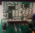
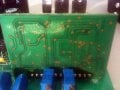
These photos are front and back of the miniboard; I don't know if that's what you want, or closeups of the larger board?

Disregard D8 in the front photo; one end of it was disconnected for testing at that time.
 

Attachments

R!f@@

Joined Apr 2, 2009
10,007
Close up of the large board so that I can actually feel like it is in my hand. I can sometimes tell a lot by looking.....

and buddy, when u take photo's go out side. Lighting and focus is essential in these matters
 

Thread Starter

pokethebear

Joined Nov 25, 2010
57
I'll do the best I can ... only had access to that camera (which is a crap camera at the best of times) at night so far. Can probably swing something tomorrow morning.

Should be finished with the schematic of main board back to the connector to the console board within about an hour
 

Thread Starter

pokethebear

Joined Nov 25, 2010
57
Schematic is finished for now. Everything is there except the incline and relay circuits, both of which are working, and the mini board. If you need the incline and relay circuits drawn, let me know.

It's messy, and some of the symbols are wrong because I still haven't located the TinyCAD libraries I need for them.

The chassis grounds shown are not actually connected to the chassis. Again I don't have the symbol I want for them. They are also not directly connected to the other common in the console board connector area.
 

R!f@@

Joined Apr 2, 2009
10,007
Referring to the diagram.

Are u certain abt the ladder network consisting of R33 to R37 and C26 to C28?

Here is a little test u can do to check if the console is working.
See the console board connection 6 & 5.

Secure the connection and all the ground terminals
Connect the board and power up.
Next put DMM is DC volt mode, connect black probe to C4 Negative. Red probe to terminal point 6 of console board.

U shud measure around 20VDC.

Leave the black probe connected
Now connect RED probe to positive side of C4 .
U shud measure 5V.

Now connect RED probe to Base of Q5, and switch on the tread from console as an operator is ready to tread. Once the console is on, u shud measure 0.6V at the base of Q5.

If the measurements are correct then proceed, if not post the result.
Now to check opto
Leave the black probe connected.

Measure pin of opto PC817, U6. U shud get 5V when tread is off, & around 1.1V when tread is in running mode.
Pin 2 of opto or emitter of Q5. U shud measure 5 V when tread is standby and 0.6V or below when tread is running.

Post the result. Go through this after understanding what U are going to do.

{ed}
Q5 shud be mirror connection. Emitter to ground, Collector to Opto
 
Last edited:

Thread Starter

pokethebear

Joined Nov 25, 2010
57
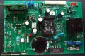
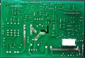
Photos attached, best I can do. Let me know if you want different angles.

R!f@@ said:
Are u certain abt the ladder network consisting of R33 to R37 and C26 to C28?
Yes, checked it again. I'll probably triple-check it a bit later

R!f@@ said:
Q5 shud be mirror connection. Emitter to ground, Collector to Opto
Thanks, that's fixed in the schematic now. I got accustomed to the datasheets showing the front of the devices, this one shows the back ... trap for young players it seems, noted for future.

Tests in progress.
 

Attachments

R!f@@

Joined Apr 2, 2009
10,007
A little dark but for now it will do...
can't see any physical problem.

Make sure you have put enuf solder from both sides on the pins of the power components.

Can you show me the console
 

thatoneguy

Joined Feb 19, 2009
6,359
Hi resolution pics of the board where pins 5 and 9 from the power board go to would be useful. As stated before, that board is fine, since the system has full function when jump-starting the SCR.

We only need to see what pin 5 and 9 from the power board (the lines to the optoisolator) are connected to and go from there.
 

Thread Starter

pokethebear

Joined Nov 25, 2010
57
If they're still needed at that time, I'll get some clear shots of the mini board and console board tomorrow morning; unfortunately that camera goes to work with my gf each day and by the time she returns it'll be dark outside.

Test results:

R!f@@ said:
Next put DMM is DC volt mode, connect black probe to C4 Negative. Red probe to terminal point 6 of console board.

U shud measure around 20VDC.
17VDC.

R!f@@ said:
Leave the black probe connected
Now connect RED probe to positive side of C4 .
U shud measure 5V.
5V.

R!f@@ said:
Now connect RED probe to Base of Q5, and switch on the tread from console as an operator is ready to tread. Once the console is on, u shud measure 0.6V at the base of Q5.
0.12V.
 

Thread Starter

pokethebear

Joined Nov 25, 2010
57
R!f@@ said:
connect meter to pin 5 of console and hit run and tell me the DC value at that point
0.17V.

However, that's with the black lead still on C4 negative, so I suppose there's a chance that it's a useless measurement if the cable has multiple issues that for some crazy reason didn't show up on a continuity test. You'd know more about that than I.

I'll locate a suitable ground on the console board in the meantime, likely wherever C4 negative makes it to the console connector.
 

R!f@@

Joined Apr 2, 2009
10,007
Ground connection won't be common as PWM uses HVDC. That part is always isolated.

If that transistor isn't switching on, then it won't ground the opto's LED. I would say according to ur schema that is the turn on or running condition.

Be ware not to common all the grounds. The grounds and earth should be as it is.
Any circuit which uses opto's will have separate ground and shud be treated as such.

Opto's are used for galvanic isolation.

Remember that console is isolated from the PWM. So use the C4 negative as console ground always. I think u are having a console issue. Can u show me that part
 

Thread Starter

pokethebear

Joined Nov 25, 2010
57
Yeah I could see in the circuit the separate 'ground' groups isolated from each other. It was evident that they were separate for a reason and so I kept them separate in the schematic.

After checking the enable signal between pin 5 in the console and C4 negative, I only did the second check between pin 5 at the console and the corresponding negative at that end of the console cable. Schematic is updated with those connections to the console btw.

I'll have to get photos of the console board in the morning when I have the camera again. I've looked at that board though, and it's ... messy ... lots of solder joints haven't flowed through to both sides, and there are a number of scratches between tracks that look like someone has had to scratch out shorts. There's also one area with a bunch of small surface-mount resistors packed onto the back of the console in a not-quite-professional manner ... anyway I'll post photos when I have them.

Thanks again for your continued help.
 

thatoneguy

Joined Feb 19, 2009
6,359
I've looked at that board though, and it's ... messy ... lots of solder joints haven't flowed through to both sides, and there are a number of scratches between tracks that look like someone has had to scratch out shorts. There's also one area with a bunch of small surface-mount resistors packed onto the back of the console in a not-quite-professional manner ... anyway I'll post photos when I have them.
That might be the issue. Something could have gotten bumped loose/tight during the moving of it.
 

Thread Starter

pokethebear

Joined Nov 25, 2010
57
R!f@@ said:
Would you mind updating ur profile, add the location and GMT.
Done. Wow that biography field is wacked in google chrome.

thatoneguy said:
Something could have gotten bumped loose/tight
Weird coincidence if it's something else. Could be anything though I guess
 
Top