Great advice. I totally forgot that when I grounded pin 2 of U2 in the console board. I'm trying to go carefully, but things can still be forgotten. While I did work very effectively as a tech, it's been a long time.
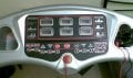
Photo attached for reference. PCB is removed from behind the face plate in the photo. Say hi to my meter.
LED displays:
---------------------
All appear to work as expected.
Time / calories / distance:
---------------------
All of these count upwards as the tread is running.
Speed:
---------------------
Slow / fast buttons decrease and increase speed as expected; status is displayed in the speed readout. The Km/h buttons alter speed almost as expected. I say 'almost', because speed 'seems' faster than it should be, only at the faster settings. That's a guess.
Incline:
---------------------
Up / down buttons increase and decrease incline in small increments. The % buttons work as expected.
Program:
---------------------
I haven't tried the programs yet, because I reasoned that the tread isn't running at all because of a different fault. I'm happy to test the programs if needed.
Pulse:
---------------------
Besides being labeled as 'pusle' this works fine up to a point; displayed heart rate maxes out at 105.
I've just ran the treadmill for around 10 minutes with no apparent faults (with the opto output still bridged).
Looking at the schema, remove R49. Or u can remove one pin of R.
Connect the board and power up the tread.
Connect meter negative to C4 negative, connect the red to pin 5 of console board.
Hit run and check the voltage change from Idle to Run.
Post back
No it's U1, its outputs, pins 4 and 6. I missed that label in the schematic, but it's updated now.
R!f@@ said:
Looking at the schema, remove R49. Or u can remove one pin of R.
Connect the board and power up the tread.
Connect meter negative to C4 negative, connect the red to pin 5 of console board.
Hit run and check the voltage change from Idle to Run.
Looking at the schema in post 85 Tell me the Voltage level at these points.
Keep the resistor out and the solder bridge at Q5 as it is for now...(which puts the tread in run mode)
Connect the board and power up. Hit run and measure
Ground terminal this time shud be the negative of C36 which is at the output of 15V reg, U4.
Post the voltage level at pin 3 & 1 of U2 (78L12)
Post the voltage level of pin 4 & 9 at mini board connector
Continue testing without changing any previous changes.
Voltage at cathode of D8 or TLP561G's pin 1 & 2
Voltage level at U6's C & E pins.
Both at idle and run
After recording all the voltages.
Desolder all the bridges that you joined, make the joints as they should be. I repeat no more bridges.
Re solder the R49.
Now everything should be as it shud. No solder jumpers and no unsoldered joints or components....Corect!
Next I want you to remove the opto U6. Desolder it and take it out....
Then find a red or green LED.
Solder it to the opto's LED connection. i.e. solder a LED to pads 1 & 2 of U6 (U6 removed).
LED's anode should be connected to pad where pin 1 is.
Now connect every thing as it is. Put the board back and power up.
Observe the LED after hitting run.
Post back what you observe from the LED.
This is to see if the processor is pulsing or what ever. We need to see since you do not have a scope.
well !!
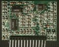
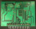
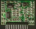
Can you probe the mini board once soldered on to the PCB. If so then put it back
If not, find some way to lift the board or may be find a way to have descent access to it when powered , for voltage measurements
I can probe most parts of the board carefully. A few parts of it are behind other components, but I'll deal with those as they come up. If necessary I can make a harness.
I'll need exact points ... as you can see the labeling isn't the best.

 Facebook
 Google
 GitHub
 Linkedin