Determine the voltage across a diode

Thread Starter

beggi9

Joined Mar 3, 2016
42
I'm in bit of a pickle with this problem
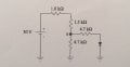
In the circuit in the attached photo
a) Is the voltage (potential difference) enough in point a so you can be sure the diode has a voltage drop of 0.7V?
b) Determine the current Id through the diode
c) Determine the voltage (potential difference) in point a.

I'm not really sure how I would go about solving this. I think the answer to a) is yes and in b) I get 3.02*10^-3A. c) 14.89V
I'm not sure however how I can calculate a) without knowing if there is a 0.7voltage drop in the diode or not. Furthermore I don't see if in b) c) I can just use 30-0.7=Rtot*Itot and just use ohm's law to figure out the rest?
All help really well appreciated!
 

Attachments

WBahn

Joined Mar 31, 2012
29,976
What model are you using for the diode?

My guess is that you are assuming that if it is "on" that it drops a constant 0.7 V regardless of the current and if is "off" then is has zero current through it regardless of the voltage (as long as the forward voltage drop is less than 0.7 V). That's a common model that produces sufficiently accurate results for the bulk of the time.

Most of the time you can determine, by inspection, whether the diode will be on or off. But let's say that you can't. How can you do it?

Pretty simple, actually. Guess and verify.

1) Flip a coin.

2) Assume a state for the diode based on which side of the coin is up:
Heads) The diode is "on".
Tails) The diode is "off".

3) Analyze the circuit based on that assumption.
Heads) If "on", then replace the diode with a 0.7 V battery (oriented to give a forward voltage drop of 0.7 V).
Tails) If "off", then remove the diode completely.

4) Verify that the choice was correct.
Heads) If "on", then the current through the supply must be in the forward direction of the diode.
Tails) If "off", then the forward voltage drop across where the diode was must be less than 0.7 V (and any negative voltage is less than 0.7 V).

5) If the verification fails, you assumed wrong. Turn the coin over and go back to Step 2.
 

Thread Starter

beggi9

Joined Mar 3, 2016
42
What model are you using for the diode?

My guess is that you are assuming that if it is "on" that it drops a constant 0.7 V regardless of the current and if is "off" then is has zero current through it regardless of the voltage (as long as the forward voltage drop is less than 0.7 V). That's a common model that produces sufficiently accurate results for the bulk of the time.

Most of the time you can determine, by inspection, whether the diode will be on or off. But let's say that you can't. How can you do it?

Pretty simple, actually. Guess and verify.

1) Flip a coin.

2) Assume a state for the diode based on which side of the coin is up:
Heads) The diode is "on".
Tails) The diode is "off".

3) Analyze the circuit based on that assumption.
Heads) If "on", then replace the diode with a 0.7 V battery (oriented to give a forward voltage drop of 0.7 V).
Tails) If "off", then remove the diode completely.

4) Verify that the choice was correct.
Heads) If "on", then the current through the supply must be in the forward direction of the diode.
Tails) If "off", then the forward voltage drop across where the diode was must be less than 0.7 V (and any negative voltage is less than 0.7 V).

5) If the verification fails, you assumed wrong. Turn the coin over and go back to Step 2.
Thank you for your answer
Yes sorry I should have said it above, I'm assuming that if it is "on" that it drops a constant 0.7 V regardless of the current and if is "off" then is has zero current through it regardless of the voltage. Okay I see where you are going so I just say that it's off or on and check if it adds up? but the question asks me to see if the voltage (potential difference) is enough in point a so I can assume that it's "on". I don't get how I can calculate the voltage in a without knowing the status of the diode?
 

WBahn

Joined Mar 31, 2012
29,976
I would read that as meaning to assume the diode is off and then calculate if the voltage across the diode would be such as to turn it on.
 

Thread Starter

beggi9

Joined Mar 3, 2016
42
I would read that as meaning to assume the diode is off and then calculate if the voltage across the diode would be such as to turn it on.
ahh I see okay but if I assume the diode is off then there would be no current over the 4.7k ohm in series with the diode right? so I can just calculate the voltage in point a as that section wasn't really there? ( in section a that is)
 

WBahn

Joined Mar 31, 2012
29,976
ahh I see okay but if I assume the diode is off then there would be no current over the 4.7k ohm in series with the diode right? so I can just calculate the voltage in point a as that section wasn't really there? ( in section a that is)
Correct.

Usually the circuit is easier to analyze when you assume the diode is off, so that is the choice that is often made when it isn't obvious that it is on.
 

Thread Starter

beggi9

Joined Mar 3, 2016
42
Correct.

Usually the circuit is easier to analyze when you assume the diode is off, so that is the choice that is often made when it isn't obvious that it is on.
Okay so I calculated that when the diode is off the Voltage in point a would be 19.583V.. how can I prove that this is "enough" to turn the diode on?
And in b do I find the current by using (9-0.7) = Rtot*Itot and then find Id from that?
 

WBahn

Joined Mar 31, 2012
29,976
Okay so I calculated that when the diode is off the Voltage in point a would be 19.583V.. how can I prove that this is "enough" to turn the diode on?
It's not the voltage at Point 'a' that matters, in and off itself. It's the voltage that appears across where the diode would be if it were there (since the assumption was that it is off, it is just as if it weren't there at all). If that voltage exceeds 0.7 V, then that is enough to turn the diode on and the assumption that it is off is invalid.

And in b do I find the current by using (9-0.7) = Rtot*Itot and then find Id from that?
Remember that Ohm's Law is very specific -- it relates a resistance to the voltage across THAT resistance and the current through THAT resistance.

What is Rtot? Can you put one finger on one end of THAT resistance and another finger on the other end of THAT resistance? Is Itot the current through THAT resistance (i.e., it MUST pass under one finger, go through THAT resistance, and then pass under the other) ? Is (9 V - 0.7 V) the voltage across THAT resistance (i.e., that's the voltage you would read if you put a pair of voltmeter probes where your fingers are).?
 

Thread Starter

beggi9

Joined Mar 3, 2016
42
It's not the voltage at Point 'a' that matters, in and off itself. It's the voltage that appears across where the diode would be if it were there (since the assumption was that it is off, it is just as if it weren't there at all). If that voltage exceeds 0.7 V, then that is enough to turn the diode on and the assumption that it is off is invalid.


Remember that Ohm's Law is very specific -- it relates a resistance to the voltage across THAT resistance and the current through THAT resistance.

What is Rtot? Can you put one finger on one end of THAT resistance and another finger on the other end of THAT resistance? Is Itot the current through THAT resistance (i.e., it MUST pass under one finger, go through THAT resistance, and then pass under the other) ? Is (9 V - 0.7 V) the voltage across THAT resistance (i.e., that's the voltage you would read if you put a pair of voltmeter probes where your fingers are).?
okay so in b how would I go about calculating Id? If I understand you correctly I have to look at each part individually.
Could I just make two equations
30-(1k+1.5k)*(I1+Id)-(4.7)*I1 = 0
30-(1k+1.5k)*(I1+Id)-(4.7)*Id-0.7=0
And find Id from that? Or am I perhaps misinterpreting?
 

WBahn

Joined Mar 31, 2012
29,976
okay so in b how would I go about calculating Id? If I understand you correctly I have to look at each part individually.
Could I just make two equations
30-(1k+1.5k)*(I1+Id)-(4.7)*I1 = 0
30-(1k+1.5k)*(I1+Id)-(4.7)*Id-0.7=0
And find Id from that? Or am I perhaps misinterpreting?
You haven't defined I1. What current is that?

You also haven't defined Id, but I am guessing that it is the forward current through the diode. The point here being that engineering is not about guessing, so don't make your readers guess.

By reverse engineering your equation (and assuming that it is correct), it would appear that I1 is the current flowing downward through the vertical 4.7 kΩ resistor.

If that assumption (another bad word in engineering) is correct, then your equations are (almost) correct.

Notice that you use 1k and 1.5k for two of the resistors but just 4.7 for the other two. That will get you into trouble.

There are other analysis techniques that you will learn that will make coming up with the needed equations a bit simpler, but these two will work fine.

Now I just need you to track your units properly. These two equations should be:

30 V - (1 kΩ + 1.5 kΩ)*(I1 + Id) - (4.7 kΩ)*I1 = 0
30 V - (1 kΩ + 1.5 kΩ)*(I1 + Id) - (4.7 kΩ)*Id - 0.7 V = 0
 

dannyf

Joined Sep 13, 2015
2,197
Chop off the branch with that resistor plus diode, and the voltage on point a is way over 0.7v so the diode is likely to be on if it is in the circuit.

Once it is in the circuit, you can treat that branch as a simple resistor, and calculating Va is easy. Once Va is obtained, go back and make sure that it is sufficient to turn on the diode.

The answer you obtained via the above approach will be very close to the one if you knew the v-i relation of the diode.
 

WBahn

Joined Mar 31, 2012
29,976
Chop off the branch with that resistor plus diode, and the voltage on point a is way over 0.7v so the diode is likely to be on if it is in the circuit.

Once it is in the circuit, you can treat that branch as a simple resistor, and calculating Va is easy.
No, you can't, because that branch does not look like a simple resistor -- it looks like a simple resistor in series with a ~0.7 V voltage source. Depending on the original calculated value for Va and the relative sizes of the resistors, it MAY be reasonable to ignore the 0.7 V voltage source, but that is far from guaranteed.
 

dannyf

Joined Sep 13, 2015
2,197
The above approach assumes an ideal diode.

If you have to consider the diodes forward voltage drop, you can do that iteratively.

First, assume no forward voltage drop and calculate Va.

From Va, calculate the current through the diode : I'd = (Va - 0.7) / 4.7k.

Once you have that, you can calculate the diodes equivalent resistance as 0.7 / Id.

You can the revise that branch's equivalent resistance.

From that, recalculate Va.

And go back to revise I'd, ......, until the solution converges.
 

dannyf

Joined Sep 13, 2015
2,197
A mathematical solution is possible.

First equation is to calculate Va from the resistive branch and then from the diode branch: they should be equal.

Then calculate the voltage drop for the whole loop based on the current over the circuit. It should sum up to 30v.

Two equations, two unknowns (current going through the bottom two branches).

Personally, I like the iterative approach.
 

dannyf

Joined Sep 13, 2015
2,197
Some numbers:

[iteration 0]assuming the diode has no voltage drop, Va = 14.53v; current through the diode is 2.94ma; the diode's equivalent resistance is 0.24Kohm;
[iteration 1]from that, Va = 14.7188v; current through the diode is 2.9827ma; the diode's resistance is 0.2347Kohm;
[iteration 2]from that, Va=14.7165v; current through the diode is 2.9822ma; the diode's resistance is 0.2347Kohm;

it pretty much stays at Va=14.72v after that.

So assuming Vfwd=0.0v gives a small error that can be corrected for the most part within 1 iteration.
 

dannyf

Joined Sep 13, 2015
2,197
The interesting scenario is when the voltage applied is so low that the diode is about to conduct (=diode's equivalent resistance = infinity). You can calculate what that voltage is.
 

Jony130

Joined Feb 17, 2009
5,487
Why OP do not try to use a thevenin's theorem ?
We simply have Vth ≈ 19.583V and Rth ≈ 1.632kΩ . And from this we already seen that Diode will be in "on".
And Id ≈ (19.583V - 0.7V)/(1.632kΩ + 4.7kΩ) = 2.98mA and Va ≈ 0.7V + (2.98mA*4.7kΩ) = 14.7V
 

dannyf

Joined Sep 13, 2015
2,197
A more convoluted but analytical way is to convert the 30v + 1K+2.5K voltage source to a (30v/3.5K) current source // 3.5K resistor. that current source, // with the 4.7k resistor -> voltage source of (30v/3.5k) * (3.5k//4.7k), with a serial resistance of 3.5k//4.7k.

From there, calculating the current through the diode is a walk in the park.
 
Top