Designing Driver Circuit

Thread Starter

Vihaan@123

Joined Oct 7, 2025
285
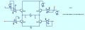
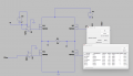
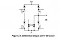
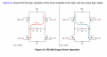
I have gone through the below TI document page number 3
1783342849041.png
1783342884697.png
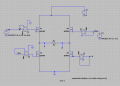
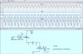
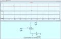
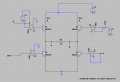
I want to simulate the fig2.2 using LTspice using transistors and main aim is to generate 1.5V with 54 Ohm load. The LTspice model is as below
1783343011513.png
According to my understanding i need to find the RC1 and RC2. Is it correct? Do i need to consider the base resistors as well? Please help to solve the circuit.
 

Attachments

panic mode

Joined Oct 10, 2011
5,083
RS485 is pretty fast so transistors should not go into saturation. they are low power high speed types and as such have significant Rds_on. to produce 1.5V across 54 Ohm you need current to me at least 1.5V/54Ohm=27.77mA.
since the supply is 5V, voltage drop across two transistors must be less than 5V - 1.5V = 3.5V or 1.75V per transistor (Assuming they are matching). so maximum resistance of one transistor is 1.75V/27.77mA = 63Ohm. designing for 20 Ohm or less give you decent safety margin.

20+54+20 = 94 Ohm.

5V/94 Ohm = 53.19mA which is practically double of the 27mA mentioned before.

so to make transistor act as 20-30 Ohm resistor, you need to bias it
btw if you want to simulate MOSFET stage, why are you using BJTs? do you know the difference? if you did, you would not bring input voltages to transistor bases like that. BJTs are current controlled devices, MOSFETs are voltage controlled devices.
this means BJTs require base resistors (series), while MOSFETs do not.
 

ericgibbs

Joined Jan 29, 2010
21,479
Hi V123,
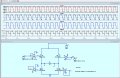
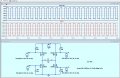
If you add the requested voltages and signals to the circuit it should highlight to You the number circuit errors in your proposed design.

E
 

Thread Starter

Vihaan@123

Joined Oct 7, 2025
285
Can you please clarify the below point, i have downloaded the data sheet of BSP89 the VGS is 1.4V and the RDS(on) is 6Ohm, so when M1 and M3 are On the total resistance is 6 Ohm + 6Ohm + 54Ohm = 66 Ohm. The current is 75mA and the voltage drop across 54Ohm = 75mA * 54 Ohm = 4.05V, how do i bring it to 1.5V, am i missing some additional circuit?
 

Thread Starter

Vihaan@123

Joined Oct 7, 2025
285
Ok i understand now that the source is floating, and the gate voltage to be more than the source by 1.4V, so need to add the bootstrap capacitor, am i correct?
 

ericgibbs

Joined Jan 29, 2010
21,479
Ok i understand now that the source is floating, and the gate voltage to be more than the source by 1.4V, so need to add the bootstrap capacitor, am i correct?
Hi V.
The source is not floating when it is positive, there is voltage drop across the 54R resistor, which pulls the Source voltage high.
How will a bootstrap cap help???

You need to study transistor theory before designing circuits
E
EG 2140.jpg
 
actual terminating resistors (found at both ends of a bus) are usually 120 Ohm and - they are in parallel. so actual load is normally 60 Ohm...
but... to ensure circuit can drive that, specs are demanding more... and that is where 54 Ohm and minimum 1.5V come from.
in reality voltage differential is higher than 1.5V (2.5-3.5V... or even up to 5V). it needs to be at least 1.5V to reliably receive data... because there can and will be not just your signal but some noise as well.
 
Top