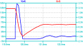
Designing custom design snubber

Thread Starter

Samantha Groves

Joined Nov 25, 2023
174
1792959802247.png


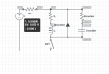
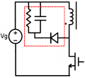
I have designed my own custom snubber circuit for a switch.The capacitor handless voltage spikes while the diode handles current spikes.However this is not the typical snubber circuit for a inductive load operating under switching conditions.What r the pros and cons of my snubber circuit in comparison with this:1792960063929.png
 

Ian0

Joined Aug 7, 2020
13,306
It depends on the purpose of the circuit.
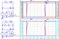
Your first circuit looks like the combination of the standard diode clamp you would use on a relay and an RC snubber, and as you can see from @Danko simulation, the diode clamps the voltage before the RC snubber has much effect. It just prevents ringing as the diode switches off. You'd have to add the intrawinding capacitance of the inductor to see if that was true in real life.
The diode clamp is fine for relays, but the low clamping voltage keeps the current flowing longer and the relay takes longer to switch off. Use the RC circuit instead, the voltage rises higher, the current stops sooner and the relay closes more quickly. The disadvantage is a higher and less easy to calculate voltage on the transistor.
Your second circuit looks like the primary side of a flyback converter. In that case the voltage must rise above the supply for the secondary to provide any output. If the operating frequency goes up, then the capacitor voltage can get pumped up higher, and will only stop at the point the transistor avalanches or the resistor or capacitor insulation breaks down.
 

Pyrex

Joined Feb 16, 2022
565
The diode clamp is fine for relays, but the low clamping voltage keeps the current flowing longer and the relay takes longer to switch off.
If the relay has to switch a heavy load, then this solution won't be good as the relay contacts won't last long.
To basically improve the snubber's properties, it's enough to connect a resistor in series with the diode.
The resistor value can be from 3x to 5x higher than the relay coil resistance. Using this circuit, you need to consider that the voltage on the transistor will increase, so it's necessary to choose a transistor with the appropriating voltage.
 

Ian0

Joined Aug 7, 2020
13,306
If the relay has to switch a heavy load, then this solution won't be good as the relay contacts won't last long.
To basically improve the snubber's properties, it's enough to connect a resistor in series with the diode.
The resistor value can be from 3x to 5x higher than the relay coil resistance. Using this circuit, you need to consider that the voltage on the transistor will increase, so it's necessary to choose a transistor with the appropriating voltage.
Especially if the relay is switching DC.
But you illustrate my point perfectly - there is no single ideal universal snubber circuit- it depends on the application.
 

Danko

Joined Nov 22, 2017
2,247
the capacitor just exists to prevent the voltage of the inductor to rise due to the big dI/dt.
In your circuit capacitor shorted by diode, capacitor does not work.
Diode limits HV pulse at level about 1 V.
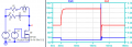
In this circuit capacitor limits HV pulse at level about 140 V without diode:
1793028644368.png
ADDED:
1793078114947.png
 
Last edited:

Externet

Joined Nov 29, 2005
2,680
My specific true need is for plain use of (circular saw, vacuum cleaner, water heater, single burner stove hot plate, drill, compressor...) circuit on 120VDC at 10 Amperes.
What design would work to protect the switch contacts from arcing, erosion and deterioration ? And how are its components calculated ?
 
You cannot use an AC-rated contactor to interrupt a large DC current. Full stop.
But rather than myself typing over a hundred words attempting to convince you, I’m instead copying an AI reply;

#######
The fundamental difference between AC and DC contactors lies in their arc extinguishing capability and magnetic circuit design. You absolutely cannot substitute one for the other at will, as this can lead to equipment damage or fire.

⚡ Core Difference: Arc Extinguishing
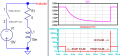
This is the most critical distinction. Alternating Current (AC) naturally passes through zero twice per cycle, and the arc extinguishes automatically at the zero-crossing point, making it relatively easy to break. Direct Current (DC), however, has no zero-crossing point, so once an arc is established, it will continuously burn, making it very difficult to extinguish.

· AC Contactors: Use grille arc extinguishing devices, relying on the zero-crossing characteristics to extinguish arcs.
· DC Contactors: Must use magnetic blowout arc extinguishing devices, utilizing magnetic force to pull and elongate the arc, thereby cooling and extinguishing it. Therefore, using an AC contactor for DC circuits is extremely prone to sustained arcing, which can burn the contacts or cause a fire.


There are special contactors for interrupting DC currents, they are significantly more expensive.
 

Thread Starter

Samantha Groves

Joined Nov 25, 2023
174
Danko replied first
Ehm no.If you agree with his answer then you are wrong too.If there wasnt any capacitor the voltage of the inductor during the transistion from ON to OFF could be anything as high as di/dt allows it. The capacitor now LIMITS the starting voltage of the inductor to the voltage drop (when the switch is ON).
 

Ian0

Joined Aug 7, 2020
13,306
Ehm no.If you agree with his answer then you are wrong too.If there wasnt any capacitor the voltage of the inductor during the transistion from ON to OFF could be anything as high as di/dt allows it. The capacitor now LIMITS the starting voltage of the inductor to the voltage drop (when the switch is ON).
di/dt is not the limiting factor. It it the breakdown voltage of whatever is in the circuit, diode, air gap, transistor etc.
 
Ehm no.If you agree with his answer then you are wrong too.If there wasnt any capacitor the voltage of the inductor during the transistion from ON to OFF could be anything as high as di/dt allows it. The capacitor now LIMITS the starting voltage of the inductor to the voltage drop (when the switch is ON).
As Danko explained:
“If the capacitor is shorted by the diode, the capacitor doesn’t work”
Keyword here: shorted.
If you don’t want to understand this, then all I can say is good luck when you actually build the circuit.
 
The arcing issue is actually more simply resolved by the means of selecting the switch device to have an adequate gap in the open condition. That works for AC switching as well. Using signal switching rated devices to switch any power will often lead to assorted problems ,icluding those being discussed.
 
Top