Hello everyone. I came across this site in search of some answers. I am designing some led tail lights for my classic car. I know there are a few out there for sale but expensive and don't really like the look. I don't have any formal training or knowledge just what I've picked up these last few weeks.
I would like to see if the schematics below would work.
Here is some info:
It will be laid out on two boards, only because of the way the tail light housing is made.
Will have an LED ring for the Park light signal
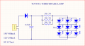
Outer pcb

Inner pcb

So if there is anything I'm missing, don't need or need to change, please I would greatly appreciate it.
Thanks,
JC
I would like to see if the schematics below would work.
Here is some info:
It will be laid out on two boards, only because of the way the tail light housing is made.
Will have an LED ring for the Park light signal
VF = 1.7V-2.5V (Would like to run them at 2.1V)
IF = 20mA
A set of LEDs for the Turn signalVF = 1.7V-2.5V
IF = 20mA
A set of LEDs for the Brake signalVF = 1.7V-2.5V
IF = 20mA
A set of LEDs for the Reverse signalVF = 2.8V-3.6V (Would like to run them at 2.8V)
IF = 20mA
Running each trigger with a 12V regulator to make sure I get constant voltage applied since it could range between 12V-14V. I have marked the desired voltage in red for each cluster of LEDs. I don't know if my understanding of how LED forward currents and resistors work but, I placed resistors to get the desired voltage drop.Outer pcb
Inner pcb
So if there is anything I'm missing, don't need or need to change, please I would greatly appreciate it.
Thanks,
JC