Designing an amplifier

Thread Starter

Mohamad Tarabah

Joined Jul 4, 2016
54
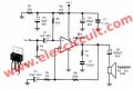
Hi everyone I saw this circuit on internet for 150w amplifier so I bought the parts of it, I want you please to check if the circuit is legit and true. Also when I went to buy TIP41 they gave me instead BD243C and said they are same. Any suggestion ?
 

Attachments

RichardO

Joined May 4, 2013
2,270
The circuit is drawn very badly. That is usually a bad sign. I took a quick glance at the circuit and it looks like it at least has a chance of working. However, I doubt that you will be able to get 150 watts out of it.

The BD243C does look like it will work in your circuit without any changes.

Keep in mind that transistors Q1 and Q2 have to dissipate the same amount of power as the speaker. This requires a really big heat sink to keep the transistors cool so they do not fail.
 

RichardO

Joined May 4, 2013
2,270
It looks like the two different pictures are of the same circuit. One is more "pictorial".

After looking at the circuit again I am thinking that it will _not_ work. there are two major problems.

The first is using 1N4007 diodes to bias the output stage. This is the wrong number of diodes to have low distortion. There should be 3 or 4 diodes to bias the Darlington transistors.

Second, even if you used the "correct" number of diodes the bias would not be right without some adjustment to the bias setting.

Third, the 1N4007 diodes must be thermally connected to the output transistors. It is going to be hard to get the diodes in good thermal contact with the heat sink.
 

crutschow

Joined Mar 14, 2008
38,504
Based upon the circuit errors noted by RichardO, I think that circuit was never built and tested, so you would be building an unproven circuit that likely won't work properly.
I suggest you look for a better circuit.
 
Last edited:

AnalogKid

Joined Aug 1, 2013
12,128
While I hate blanket generalizations, here's one: That is a bizarre way to draw a schematic that has been in general circulation around the world for over 50 *years*, and I would not trust anything from someone so disconnected from or dismissive of conventions and standards.

Also, getting 150 W of audio from just two output transistors is possible, but it will run the components very near their electrical and thermal limits. It is reasonable to think you can whip up a 5 W or 10 W audio amplifier with little more than a schematic. But anything over 20-30 W needs much more careful physical layout, power quality, ground management, and some serious cooling.

I suggest you start out at a lower power level, maybe with a kit off of ebay, and learn at that level before moving to higher power levels.

ak
 
Last edited:

dannyf

Joined Sep 13, 2015
2,197
if the circuit is legit
it is legit (in that it will produce some sound).

it is not legit in that there is no way it can produce that much sound, and no likely quality sound.

two suggestions: 1) you can do better, if you want; 2) you may want to build a smaller one to begin with. 150w rms is a lot of power for most people. power supply, heatsinks and case are where you spend most of your money on, in that order.
 

bertus

Joined Apr 5, 2008
22,923
Hello,

Here are two other designs.
One old design for a 120 Watt amplifier from elektor:
120_watt.jpg
And an other 250 Watts (handdrawn by some one else):
250wamplifier.jpg

Bertus
 

dannyf

Joined Sep 13, 2015
2,197
not in the same league with your tip-based power amp in terms of output power and sound quality, AKSA 50 is a great little amp. The schematic comes with the kit but there is an open source version of it - an earlier version of the AKSA 50.

Building that would be infinitely better than building your own.
 

Thread Starter

Mohamad Tarabah

Joined Jul 4, 2016
54
Hi everyone, thanks again
I did as you told me and made a small 20w version with the old and popular IC LM1875
Just before I solder it I want you to check if this circuit works, unfortunatly I bought the parts of this circuit and not those of the one that comes with the datasheet.
 

Attachments

bertus

Joined Apr 5, 2008
22,923
Hello,

The LM1875 is basicaly a power opamp.
Just have a look at the datasheet:
LM1875
The shown schematic is taken from the datasheet figure 2

Bertus
 
Top