 Facebook
 Google
 GitHub
 Linkedin
Hi Guys,
Im studying for an electronics exam and I came past a question which I have started but finding it hard to finish.
The question is
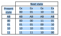
Design a sequential circuit with two JK flip-flops, A and B, and two inputs, E and x. If E = 0, the circuit remains in the same state regardless of the value of x. When E = 1 and x = 1, the circuit goes through the state transitions from 00 to 01 to 10 to 11 back to 00, and repeats. When E = 1 and x = 0, the circuit goes through the state transitions from 00 to 11 to 10 to 01 back to 00, and repeats.
I have created the truth table which I have attached.
Im not sure How to get the equations to create the circuit.
Please help?
Im studying for an electronics exam and I came past a question which I have started but finding it hard to finish.
The question is
Design a sequential circuit with two JK flip-flops, A and B, and two inputs, E and x. If E = 0, the circuit remains in the same state regardless of the value of x. When E = 1 and x = 1, the circuit goes through the state transitions from 00 to 01 to 10 to 11 back to 00, and repeats. When E = 1 and x = 0, the circuit goes through the state transitions from 00 to 11 to 10 to 01 back to 00, and repeats.
I have created the truth table which I have attached.
Im not sure How to get the equations to create the circuit.
Please help?
Attachments
-
 37.3 KB Views: 98


