Facebook
 Google
 GitHub
 Linkedin
Hi All,
I am creating a linear power supply 0-18V, 0-3A and I have a transformer with a 19-0-19 VAC center tap, 25-0-25 VAC center tap, and two 15VAC windings
(120VAC input).
The 19-0-19 VAC center-tapped side will be used to create a voltage splitter ---> +/- 5V for the opamps and references on the op-amps and the 25-0-25 center-tapped side will be used for the input side to the pass transistor.
My question is how to implement a relay switch to move from 50VAC input to 25VAC input(moving from 25-25 to 0-25) when the load current goes very high?
I have seen some examples such as the solid state version:

However I don't want a LM317 in series with my pass transistor, instead I want to use one of the 15VAC ---> rectify for DC ---> into a voltage regulator and use that voltage for a relay with some kind of feedback from the mains output.
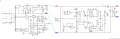
Something similar to this setup

However I don't understand how the relay is switched with this schematic. I also don't see a ground reference point for the 12 volt regulator!
I am creating a linear power supply 0-18V, 0-3A and I have a transformer with a 19-0-19 VAC center tap, 25-0-25 VAC center tap, and two 15VAC windings
(120VAC input).
The 19-0-19 VAC center-tapped side will be used to create a voltage splitter ---> +/- 5V for the opamps and references on the op-amps and the 25-0-25 center-tapped side will be used for the input side to the pass transistor.
My question is how to implement a relay switch to move from 50VAC input to 25VAC input(moving from 25-25 to 0-25) when the load current goes very high?
I have seen some examples such as the solid state version:
However I don't want a LM317 in series with my pass transistor, instead I want to use one of the 15VAC ---> rectify for DC ---> into a voltage regulator and use that voltage for a relay with some kind of feedback from the mains output.
Something similar to this setup
However I don't understand how the relay is switched with this schematic. I also don't see a ground reference point for the 12 volt regulator!