Designing a real buck converter I have run into a unsolved issue.

Thread Starter

Samantha Groves

Joined Nov 25, 2023
186
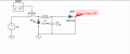
Hello.So I want to build a buck converter on a breadboard.The PWM frequency will be close to 1000Hz and I will be using a 2.2mH inductor.

I want my buck converter to operate in CCM.The target output voltage is 6.5V bcs I want to be able to power a RGB led.I am targeting at a continuous current of 10mA which means ripple current cannot be above 10mA if I want it to run in CCM and preferable 1mA ripple current is the target.

Well the math dont workout.For a 6.5V target output at Vin = 100V at 1000Hz oscillation frequency and a 2.2mH inductor the ripple current is much larger than 10mA let alone 1mA which is the target.Any solutions?
 

panic mode

Joined Oct 10, 2011
5,470
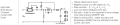
making correct schematics would also be a good start. you have N-MOS there and it is wired backwards. for that to work it would be P_MOS but driving it need to be handled. or.. keep N-MOS but wire it on the low side... and what do you want with 6.5V at GND?
what is the EXACT model of the RGB LED that you want to drive? why are you using 100V as supply? why use switching at all if you are looking at 10mA LED current?
 
Last edited:

Danko

Joined Nov 22, 2017
2,256
I am targeting at a continuous current of 10mA
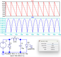
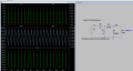
At Vin = 100 V, f =100 kHz and PWM = 3.1072 %, average current through L1 is
10.001 mA, and that current is continuous (uninterrupted), in range 3 - 17 mA.
ripple current cannot be above 10mA if I want it to run in CCM and preferable 1mA ripple current is the target.
Ripple current through LED is 0.0736 mA peak-peak.
1794876220409.png
 

Attachments

Last edited:

MisterBill2

Joined Jan 23, 2018
28,607
At 1000 Hz humans will not see any flicker in the light intensity. Of course, that depends on the source reverse impedance, doesn't it? Probably a source series diode would resolve any issue.
 

ronsimpson

Joined Oct 7, 2019
4,897
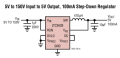
If I was making a 100V to 5V buck at less than 100mA, this is a good example.
1794942887009.png
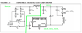
LEDs normally are driven by current not voltage. Here is an example of a 20mA LED driver that works well at 100Vdc. Its job is to make 20mA at any voltage.
1794943737269.png
 
Last edited:

ronsimpson

Joined Oct 7, 2019
4,897
How did you get on with the LTC3639
It is too much money, and I found a different way.

Here is the part I like for LED drivers. It is about 50 cents. In this mode it regulates current not voltage. Current is set by choosing Rsense for 1.65V across it. Input can be voltage from 50V to 400V. (The output is negative. Note the LEDs appear to be pointing up not down. That is the way it works.)
1794945045723.png
 

panic mode

Joined Oct 10, 2011
5,470
that is all great but did anyone ever do that to an RGB LED?
why drive RGB LED that consumes 10mA from 100V? on a breadboard? what RGB LED has IF of 10mA and Vf of 6.5V? how this this turn from lighting up and RGB led to mains illumination?
why don't we hold on until we see the real part number with actual specs?
 
Last edited:
The 1 kHz number is the killer here. With 93.5 V across the 2.2 mH inductor for about 65 us on-time, ripple is roughly 2.8 A peak-to-peak, not 1 mA. At 100 kHz it drops to about 28 mA, still too much for 10 mA in CCM — you'd need roughly 47 mH at 100 kHz for 1 mA ripple. Much easier to prototype from 24 V first: at 100 kHz with a 10 mH inductor the ripple is about 5 mA, and the loop is a lot safer to debug before you touch 100 V.
 
Top