Designed a digital lock which keeps failing

Thread Starter

AunikAhmed

Joined Dec 2, 2017
6
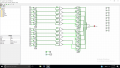
I am designing a very basic digital lock as my final project for my Logic Design class. I made my design so that it only opens if someone presses 0158 from a number of buttons I have set up. Everything works fine except when I press 0 to 9 in a continuos sequence and the lock opens even when it's not supposed to. This is my first class with combinational logic and I'm not sure how to fix my problem. I want to make it so that any other input other than 0158 would not unlock my lock. I have will attach the picture of my circuit and I will appreciate any suggestions and help I can get. Thank you in advance.
 

Attachments

kubeek

Joined Sep 20, 2005
5,796
Can you describe how it is supposed to work? I don´t really get it, especially what is the en signal supposed to be. Do you have to press that with each input?
 

Thread Starter

AunikAhmed

Joined Dec 2, 2017
6
Can you describe how it is supposed to work? I don´t really get it, especially what is the en signal supposed to be. Do you have to press that with each input?
So basically when the EN input is 1, the system turns on and the lock is locked. I connected the EN with all the gates so that when I make the EN input 1, the lock starts working. I will enter inputs using the buttons 0-9 afterwards. The inputs will pass through the first set of D flip flops to store their values, which will be then passed to the XNOR gates to see if they match the pre-existing inputs that I will have set up (0158) and then they will pass through the second set of D flips flops to see if the sequence of 0158 is right or not. This is to ensure that the sequence of 0158 is pressed, if anything else like 1058 or 0185 is pressed, it will not unlock it. But the problem is, if I enter 0,1,2,3,4,5,6,7,8,9 it still unlocks it. I know there is something wrong with the connections with the second set of filp flops, but I can't figure it out on my own.
 

dl324

Joined Mar 30, 2015
18,339
Circuit in question; edited to remove extraneous information and whitespace:
upload_2017-12-4_11-33-57.png
Your circuit has no logic to enforce the order of the digits.
 

Thread Starter

AunikAhmed

Joined Dec 2, 2017
6
Circuit in question; edited to remove extraneous information and whitespace:
View attachment 140901
Your circuit has no logic to enforce the order of the digits.
Thank you, do you have any suggestions for how to include the logic? I am trying again from scratch. This time I'm using K-maps. I'm making a state table where I will have 3 inputs a,b and c to represent 0-7. I don't know what to do next, but I will be trying different approaches to see what I can do next.
 

kubeek

Joined Sep 20, 2005
5,796
Allright, first of all I thnk the XNORs need to be NANDS, because otherwise thir outputs influence the FF chain on the right side and can lead to that case when you press all the buttons in a row and it lets you in.
Second, to make it truly adjustable without rewiring would need an awful lot of logic and wiring, are you going to build this or just simulate?
 

Thread Starter

AunikAhmed

Joined Dec 2, 2017
6
Allright, first of all I thnk the XNORs need to be NANDS, because otherwise thir outputs influence the FF chain on the right side and can lead to that case when you press all the buttons in a row and it lets you in.
Second, to make it truly adjustable without rewiring would need an awful lot of logic and wiring, are you going to build this or just simulate?
I just have to simulate it. So I can rewire wherever it is necessary. Thank you for you suggestion.
 

kubeek

Joined Sep 20, 2005
5,796
Then I would set it up so that the inputs allow a 1 to cascade through 4 FFs, and any other number just resets them.The output of the last FF would be the open/closed output.
If you then want to go fancier, you could add some selection logic to allow you to program which number goes to which FF, and make the rest go to the reset wire.
 

dl324

Joined Mar 30, 2015
18,339
Thank you, do you have any suggestions for how to include the logic?
Since this is homework, we don't just give answers. Even if it wasn't homework, I wouldn't normally just give a solution. Even people not studying electronics sometimes enjoy the challenge of doing something new so they'll have a sense of accomplishment.

To enforce order, I'd use a memory element to store the required digits and order. That's what I did when I designed a combination lock 4 decades ago (for my hobby, not school).
 

Thread Starter

AunikAhmed

Joined Dec 2, 2017
6
Since this is homework, we don't just give answers. Even if it wasn't homework, I wouldn't normally just give a solution. Even people not studying electronics sometimes enjoy the challenge of doing something new so they'll have a sense of accomplishment.

To enforce order, I'd use a memory element to store the required digits and order. That's what I did when I designed a combination lock 4 decades ago (for my hobby, not school).
Thank you for the suggestion.
 

WBahn

Joined Mar 31, 2012
32,883
The first thing is to consider how YOU would do this if YOU were the lock. Or, even better, how you would tell a five year old to do it if THEY were in the box and only had your instructions to go on.

You have 10 number inputs and a RESET input and an EN input.

So you might tell them that when they see that the RESET button is pressed, that they lock the door and the erase all of the marks on a dry erase board on which you have written, in permanent marker, 0-1-5-8 and also the words FAIL and UNLOCK. I'm going to ignore the EN input because your description didn't give me a good understanding of how you want it to behave, so I'll just pretend you only have RESET.

Now, they wait until a button is pressed. When the button is pressed and it isn't RESET, then see if the word FAIL or UNLOCK is circled. If either is, then do nothing. If it isn't, then you see if the button matches the first number in the list that doesn't have a mark under it. If it does, then you put a mark under it and, if it is the last button in the list, you also circle the word UNLOCK. If it doesn't match, you circle the word FAIL. Then you go back to waiting.

If you can produce an algorithmic description of you solution, then you are in a great position to start turning it into a logic circuit. The first step is to identify what information the kid in the box must keep track of between button presses in order to do the job. You will need some kind of memory element to store that same information.
 

Thread Starter

AunikAhmed

Joined Dec 2, 2017
6
The first thing is to consider how YOU would do this if YOU were the lock. Or, even better, how you would tell a five year old to do it if THEY were in the box and only had your instructions to go on.

You have 10 number inputs and a RESET input and an EN input.

So you might tell them that when they see that the RESET button is pressed, that they lock the door and the erase all of the marks on a dry erase board on which you have written, in permanent marker, 0-1-5-8 and also the words FAIL and UNLOCK. I'm going to ignore the EN input because your description didn't give me a good understanding of how you want it to behave, so I'll just pretend you only have RESET.

Now, they wait until a button is pressed. When the button is pressed and it isn't RESET, then see if the word FAIL or UNLOCK is circled. If either is, then do nothing. If it isn't, then you see if the button matches the first number in the list that doesn't have a mark under it. If it does, then you put a mark under it and, if it is the last button in the list, you also circle the word UNLOCK. If it doesn't match, you circle the word FAIL. Then you go back to waiting.

If you can produce an algorithmic description of you solution, then you are in a great position to start turning it into a logic circuit. The first step is to identify what information the kid in the box must keep track of between button presses in order to do the job. You will need some kind of memory element to store that same information.
Thank you so much, that actually explains a lot. All this time I have been thinking about it the wrong way. I see what you mean, I'll first create a state table then, draw up a new logic afterwards, and then put it into the simulation.
 

dl324

Joined Mar 30, 2015
18,339
Another thing you should be aware of is that you can't use a flip flop as you're doing in the top right flip flop below:
upload_2017-12-4_13-53-40.png

The flip flop will have a minimum setup time for the data input. This is the amount of time that data needs to be stable before the clock pulse.

By connecting both to the same signal, you probably won't get the expected results.

This is the data for CD4013:
upload_2017-12-4_13-56-28.png
upload_2017-12-4_13-56-47.png

Data setup time could be as long as 40ns.

Your logic symbol implies the flip flop is clocked on the rising edge of the pulse. That means before the rising edge, the logic level was LOW. So instead of a HIGH being propagated through the flip flop, you'll get a LOW.

I don't know what your simulator does with respect to setup and hold times, but this is something you need to handle in your design process.
 
Top