Derive the equation for an RC circuit

Thread Starter

KevinEamon

Joined Apr 9, 2017
284
Hey guys. Emo for today is sad face smiley... :(

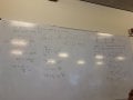
So I'm rolling along second year just fine. Ok its hard but do-able. Then this demonic entity finds it's way to the whiteboard.


First of all what the heck? Secondly I don't even know where to begin or what question to ask.
As far as I remember this was a basic RC series circuit, then he began deriving this equation.
We will be expected to derive these types of equations to start with and also much more complicated circuits.

I done quite well in calculus last semester, so I'm not a complete n00b no more. But this looks to be above my pay grade.

Ok so I guess I want to go back to first principles here. I need to learn how to do this type of thing. It looks like RLC circuits in time domain rather than phasor. Is that correct?
I guess I'm looking for power words or information so I can research this. Anything really to get me going in the right direction.
 

WBahn

Joined Mar 31, 2012
29,976
I can't read all of the writing -- and there's some stuff that is cutoff over to the right that looks relevant. For some reason, Vt = V/2 and Rt is equal to something that is missing. I'm guessing 3R/2.

Other than that, it is nothing more than the solution to a first-order RC circuit in the time domain by solving the corresponding differential equation. This is why we invented phasor techniques and why we use transform methods -- to avoid having to solve differential equations. But it is certainly reasonable to expect you to be able to do so, especially for the basic cases such as this.
 

wayneh

Joined Sep 9, 2010
17,496
If you start with the things you know, such as the voltage on a capacitor as a function of the charge, how charge relates to current and time, and Ohm's law for voltage, current and resistance, it's not that tough. Your teacher seems to have avoided using Q, charge, but it's in there.
 

Thread Starter

KevinEamon

Joined Apr 9, 2017
284
Thanks Wayneh. I guess I'm just expelling some trepidation. It just looks like a monster with fangs n claws at the moment. But I have a few months to tame the beast...

Yeh if it only were that equation, I'd just learn it off Wbahn. It's not though. I think I've uploaded a PDF with all the potential questions for the module. Now RLC circuit analysis questions I can do. If you remember we done a few together last year. So for instance the first 4 questions on the PDF are fine. It's things like questions 5, 7, 9, 10, and ---- 13 !!! wth??? and on and on lul... sigh... I'm so doomed.
 

Attachments

WBahn

Joined Mar 31, 2012
29,976
Thanks Wayneh. I guess I'm just expelling some trepidation. It just looks like a monster with fangs n claws at the moment. But I have a few months to tame the beast...

Yeh if it only were that equation, I'd just learn it off Wbahn. It's not though. I think I've uploaded a PDF with all the potential questions for the module. Now RLC circuit analysis questions I can do. If you remember we done a few together last year. So for instance the first 4 questions on the PDF are fine. It's things like questions 5, 7, 9, 10, and ---- 13 !!! wth??? and on and on lul... sigh... I'm so doomed.
What's hard about #13?

Or, said another way, try to articulate what it is about #13 that is causing you difficulty.

There's some ambiguity in the schematic since they don't show a connection dot at the wire crossing near the inverting input of the left opamp, so we don't know if they are connected or not. So solve it both ways. If there is no connection, then the left opamp has no feedback and acts like a comparator. Perhaps this is what was intended. But more likely there is a connection there. In which case it is the cascade of two very basic classic opamp circuits. There just happen to be two resistors that, in the case of an ideal opamp, have no impact and are just there to confuse you. If they ARE confusing you, then that is an indication that you aren't able to apply the fundamental opamp concepts to arbitrary circuits.
 
Last edited:

MrAl

Joined Jun 17, 2014
11,389
Thanks Wayneh. I guess I'm just expelling some trepidation. It just looks like a monster with fangs n claws at the moment. But I have a few months to tame the beast...

Yeh if it only were that equation, I'd just learn it off Wbahn. It's not though. I think I've uploaded a PDF with all the potential questions for the module. Now RLC circuit analysis questions I can do. If you remember we done a few together last year. So for instance the first 4 questions on the PDF are fine. It's things like questions 5, 7, 9, 10, and ---- 13 !!! wth??? and on and on lul... sigh... I'm so doomed.
Hi,

Well what have you actually learned in the past already?

Did you learn nodal analysis for example?
Did you learn about how to determine initial conditions for elements like the inductor and capacitor?
Did you learn about the final values?

It helps to find out what you know already so that we have some basis to work from.

In the few circuits you show it looks like they want you to understand how to write equations, both using frequency and time. Some would be in time others in frequency.
 

Thread Starter

KevinEamon

Joined Apr 9, 2017
284
Sorry guys sorry... I guess I just freaked out. Now I know why most lecturers give out their notes in a piece by piece fashion, rather than the "whole mountain."

I took a little break from study for a few hours, just to collect myself.

Btw Wahn you were right about 3(R/2). I saw it pop up again in another derivation for tutorial today. I've begun to recall, how to calculate op-amps as well, so number 13 isn't so bad anymore.
I've covered op amps, Mr AI - I've done linear circuit analysis with Dc, doing Ac this year. I've done RLC circuits in Dc. Now derivations was always something the lecturer done. I'm fine with numbers, but this is new to me.

I guess I just need resources. Any good books you could recommend? If you were to google this, what search expression would you use?
Does this style of derivation have a title? There seems to be a few alternatives, as to how you can derive and calculate these expressions; from my research so far. I've attached another example of this type so you guys can see.

This is the start of week 3, by week 6, I need to be able to look at the circuit and then do all this jazz and the more complicated ones, that are coming.
 

Attachments

WBahn

Joined Mar 31, 2012
29,976
I'm assuming you've taken a course in linear differential equations. No?

If so, recall that there are many techniques at your disposal to solve LDEs. Go back and review them and give them a try.
 

MrAl

Joined Jun 17, 2014
11,389
Sorry guys sorry... I guess I just freaked out. Now I know why most lecturers give out their notes in a piece by piece fashion, rather than the "whole mountain."

I took a little break from study for a few hours, just to collect myself.

Btw Wahn you were right about 3(R/2). I saw it pop up again in another derivation for tutorial today. I've begun to recall, how to calculate op-amps as well, so number 13 isn't so bad anymore.
I've covered op amps, Mr AI - I've done linear circuit analysis with Dc, doing Ac this year. I've done RLC circuits in Dc. Now derivations was always something the lecturer done. I'm fine with numbers, but this is new to me.

I guess I just need resources. Any good books you could recommend? If you were to google this, what search expression would you use?
Does this style of derivation have a title? There seems to be a few alternatives, as to how you can derive and calculate these expressions; from my research so far. I've attached another example of this type so you guys can see.

This is the start of week 3, by week 6, I need to be able to look at the circuit and then do all this jazz and the more complicated ones, that are coming.
Hi,

From what you have shown it looks like they want you to do those circuits with some analysis technique like Nodal or Loop using pure calculus. In that case you have to know the relationships for the cap and inductor, as well as an analysis technique. Those two would be the most important.

So the question is, what analysis techniques have you learned in the past, and do you understand integral and differential forms for the inductor and capacitor?

Some of this isnt that hard really but you have to do a few problems to get the hang of it, as long as you have some kind of analysis technique to work with like Nodal or Loop.

Let me give just one example here. A parallel RLC circuit driven by a current source i(t).
By parallel i mean all four of those elements are in parallel, and graphically the current source points UP.

We know in a parallel circuit that the current splits, but the total current is the sum of currents through all elements.
Since we have three passive elements and one source, we assume that the current source powers all three elements.
For now, there is no initial energy in any of L or C.
We can write:
v/R+C*dv/dt+(1/L)*integral[0 to t] v dt = i(t)

The variable 'v' here is the voltage across all four elements and varies with time so it is really v(t). It is neater to just write 'v'.

So all we did was sum all the passive element currents and set that equal to the current source current. We used the differential form of the capacitor and integral form of the inductor.

I am hoping you are familiar with forms like this:
i=C*dv/dt
v=L*di/dt

and we got the integral form for the inductor from the second one:
v=L*di/dt
(1/L)*integral v dt = i

so using the first above i=C*dv/dt and the last integral above we were able to sum the currents, also using Ohm's Law for the resistor i=v/R.

Does any of that make sense to you?
 

Thread Starter

KevinEamon

Joined Apr 9, 2017
284
Yes it does Mr AI. Though for some reason I remember the inductor being: (-L(dv/dt)). Perhaps that is when the inductor has some initial charge though?
The more I look at the thing, the less threatening it becomes. I'm trying to picture it naked. A naked RLC, with its derivatives hanging out :D
 

WBahn

Joined Mar 31, 2012
29,976
Yes it does Mr AI. Though for some reason I remember the inductor being: (-L(dv/dt)). Perhaps that is when the inductor has some initial charge though?
The more I look at the thing, the less threatening it becomes. I'm trying to picture it naked. A naked RLC, with its derivatives hanging out :D
The inductor is v(t) = L·di(t)/dt

Let's look at the units of

-L(dv/dt)

L has units of Henries, which are V·s/A. So L(dv/dt) would have units of V²/A or V·Ω.

Doesn't sound very meaningful.
 

MrAl

Joined Jun 17, 2014
11,389
Yes it does Mr AI. Though for some reason I remember the inductor being: (-L(dv/dt)). Perhaps that is when the inductor has some initial charge though?
The more I look at the thing, the less threatening it becomes. I'm trying to picture it naked. A naked RLC, with its derivatives hanging out :D
Hi again,

There are two forms for the inductor:
1. v=L*di/dt
2. v=-L*di/dt

The second form is more often written:
E=-L*di/dt

where E represents "emf" electromotive force.

The first form is found in CIRCUIT ANALYSIS while
the second form is found in PHYSICS.

Now the obvious question is, isnt circuit analysis part of physics. It certainly is, but in physics it is more common to work with ELECTRON current flow, while in circuit analysis it is much more common to work with CONVENTIONAL current flow.
Electron flow is said to flow from the negative of the battery through the circuit to the positive of the battery, while conventional current flow is said to flow from the positive of the battery through the circuit to the negative of the battery. So we see two different directions for the current flow, depending on the context of the discussion.

In pure circuit analysis we see conventional flow (leads to v=L*di/dt) because it makes things simpler.
In pure physics we see electron flow because it relates better to other physical quantities. This leads to v=-L*di/dt because it is derived from the change in flux v=-N*dPhi/dt which is Faraday's Law of Induction.

For every day electrical circuit analysis we use conventional flow, so unless you are working in a physics course where you need to take into account other physical things like flux then you should use conventional current flow which leads to the simpler v=L*di/dt.

As a side note, the expression E=-L*di/dt does not violate any units rules though because the current is electron flow, so the units for everything should come out the same.

As to your learning though, did you study the RL and RC circuits first? That should come first. You'll get the hang of doing these circuits and then carry that over to the RLC circuit.
 

Mark Hughes

Joined Jun 14, 2016
409
@KevinEamon,
I stumbled upon your post just today. The two things that got me through this sort of thing (back in the day): Schaum's Outlines and practice (until you can derive start to finish without looking at notes). I think I'd add a few new things if I had to do it again today.
1) I'd use color throughout the solution. I started doing this much later in life, but now whenever I'm taking notes, deriving things, etc... I use a variety of different colored pens. I don't have a particular system I worry about, just as I go and as I see patterns, I try to isolate them in a particular color. When you come back to review it later, the color will make it easier to see how things move around the page and easier to follow. (You know it now, you won't need it three months from now. Prepare for that.)
2) When possible (and it's not always possible), I use a specific format for solving problems that follows the pattern G.U.E.S.S. Givens: Write down all of the information given in the problem (e.g. R=3 Ω, I=2 A), Unknowns: Identify the unknown quantities -- what is the problem asking for?(e.g. V). Equation: Figure out what equations are pertinent to what you are doing, using the variables identified in the first two steps (e.g. V=I*R). Substitute: Substitute the variables into the equations (e.g. V=2 A*3 Ω). Solve: Now start manipulating, moving, consolidating, and evaluating (e.g. V=6 A*Ω=6 V). When I first started, I would just start grabbing numbers and throwing them into equations and going for it. The trouble with this approach is that if you make a misstep, it's difficult to find it later, and difficult for your professor to readily identify. Essentially, I was getting ahead of myself and getting in an unnecessary hurry.
 

Thread Starter

KevinEamon

Joined Apr 9, 2017
284
Thanks guys I've been putting this off for a few days now... I'm going to have to man up and tackle it. Some good advise Mark. I think I'll end up using a different methodology. Some of the lecturers looks unnecessary and over extravagant. But thanks for the great support and advise. I'm going to tackle it soon
 

Mark Hughes

Joined Jun 14, 2016
409
Thanks guys I've been putting this off for a few days now... I'm going to have to man up and tackle it. Some good advise Mark. I think I'll end up using a different methodology. Some of the lecturers looks unnecessary and over extravagant. But thanks for the great support and advise. I'm going to tackle it soon
@KevinEamon,
You have to know yourself -- and it sounds like you do. Ask for, and be receptive to advice -- and it sounds like you are. Find what works for you -- a bit of experimentation, and a bit of self-evaluation. From what I've read just today -- you'll be just fine.
The neurons in your brain are constantly rewiring themselves -- you just have to give them the opportunity, the direction, and the time to do it. It's like exercise -- nobody runs a marathon on day one. You have to put the time in and let your body/brain adapt.
BTW -- You're taking the right approach -- asking questions well in advance, and giving yourself time to think about things. If you doubt yourself for a second -- might I direct your attention to an alternate methodology that I don't believe will be quite so successful , shown at the end of the comment section of this article:
Mark
 
Top