Denon DRA-545R Stereo Receiver - No Speaker Output

drc_567

Joined Dec 29, 2008
1,156
... Not really sure what those resistance measurements indicate.
There is a similar capacitor, C405, that should be good. It is in the same area as the speaker relay that you tested previously.
Try testing the resistance across that capacitor once with the test leads in one position, and then switch the test leads around, and test the resistance again using the reverse lead polarity.
... edit:
That C405 may not be the best choice to test, because it has a parallel 1k resistor, and will normally come to rest at a reading of 1k ohms. ...
... Looking for another one to check.
 
Last edited:

drc_567

Joined Dec 29, 2008
1,156
... found another 10u/50 volt capacitor. Maybe it will be a better choice than the C405 capacitor.
See if you can find C662. It is located on the tuner board, IU-2347, just before the input to the voltage regulator, IC604.
Try the lead reverse method, where you get a resistance measurement with the test leads normal and then reversed.
 

Thread Starter

q4#W$7#y

Joined Aug 13, 2020
42
... found another 10u/50 volt capacitor. Maybe it will be a better choice than the C405 capacitor.
See if you can find C662. It is located on the tuner board, IU-2347, just before the input to the voltage regulator, IC604.
Try the lead reverse method, where you get a resistance measurement with the test leads normal and then reversed.
Sorry, had to run out for a bit. OK, I checked C662, however, I'm not sure how confident I am in the results. Normal direction initially measured 30k but began steadily creeping up past 50k. Reverse started ad -20k with the measurement steadily dropping back to 0. I'll retest in a little while to confirm.
 

Ylli

Joined Nov 13, 2015
1,092
I don't think resistance measurements are going to tell you alot. I'd suggest you measure and post the voltage readings on the emitter, base, and collector of TR417. Be careful when probing with power on, a short is not a good thing.
 

Thread Starter

q4#W$7#y

Joined Aug 13, 2020
42
I don't think resistance measurements are going to tell you alot. I'd suggest you measure and post the voltage readings on the emitter, base, and collector of TR417. Be careful when probing with power on, a short is not a good thing.
Ylli, hi.

Sure, my readings below.

Base: 5V
Collector: 5.6V
Emitter: 5.7V
 

MrChips

Joined Oct 2, 2009
35,018
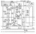
You have narrowed the fault down to the -16V power supply.

Denon DRA-545R LV power supply.jpg
First suspects are TR417 and TR419.
With power off and unit unplugged, look for shorts across b-c-e leads on these transistors while still in circuit.
 

Ylli

Joined Nov 13, 2015
1,092
drc_567 did a great job in getting you to this area of the circuitry.

That resistor (R432) is open. Now the question is why? That resistor acts as a fuse in line with the -16 volt regulator. Could have been some form of transient from your previous repair work, so first thing to try would be to just replace it with a 4.7 ohm, 1/4 watt resistor. Because it is acting as a fuse, I would not suggest you use any higher power rating (no 1/2W, etc).

If you have a Dim Bulb Tester*, power up through that. If not, just go for it and see if the new 4.7 ohm resistor remains intact. You should have -16 volts at the emitter of TR417 and less than 1 volt dropped across R432.

*power cord with an incandescent bulb in series to dynamically limit current.
 

drc_567

Joined Dec 29, 2008
1,156
... @q4#W$7#y
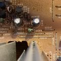
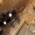
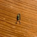
Just curious, ... would it be possible to post some kind of picture or photo of the blown resistor? ...before you remove it?
 

Thread Starter

q4#W$7#y

Joined Aug 13, 2020
42
drc_567 did a great job in getting you to this area of the circuitry.

That resistor (R432) is open. Now the question is why? That resistor acts as a fuse in line with the -16 volt regulator. Could have been some form of transient from your previous repair work, so first thing to try would be to just replace it with a 4.7 ohm, 1/4 watt resistor. Because it is acting as a fuse, I would not suggest you use any higher power rating (no 1/2W, etc).

If you have a Dim Bulb Tester*, power up through that. If not, just go for it and see if the new 4.7 ohm resistor remains intact. You should have -16 volts at the emitter of TR417 and less than 1 volt dropped across R432.

*power cord with an incandescent bulb in series to dynamically limit current.
Great work! OK, it looks like I have the correct resistor on hand so I'll swap that. Fingers crossed that's all it is. I also think I have most of the parts to construct a Dim Bulb Tester so I'll do so before powering it up just in case.

Thanks again to all of you and especially to drc_567 for getting the ball rolling on this and bearing with me. I can't tell you all enough how much I appreciate your help.
 

Thread Starter

q4#W$7#y

Joined Aug 13, 2020
42
... @q4#W$7#y
Just curious, ... would it be possible to post some kind of picture or photo of the blown resistor? ...before you remove it?
Absolutely. Will update with an image of it. Again, thanks for all your help on this.

Update: attached are images of the blown resistor (R432). It was kind of tough to get a good shot of it in place. Also included a shot of it removed.
 

Attachments

Last edited:

Thread Starter

q4#W$7#y

Joined Aug 13, 2020
42
You have narrowed the fault down to the -16V power supply.

View attachment 230491
First suspects are TR417 and TR419.
With power off and unit unplugged, look for shorts across b-c-e leads on these transistors while still in circuit.
MrChips, before replacing the resistor I went ahead and checked both TR417 and TR419 and there is continuity between the collector and emitter of TR417. Does that mean that this part is bad? TR419 exhibited no continuity between the B-C-E.
 

MrChips

Joined Oct 2, 2009
35,018
MrChips, before replacing the resistor I went ahead and checked both TR417 and TR419 and there is continuity between the collector and emitter of TR417. Does that mean that this part is bad? TR419 exhibited no continuity between the B-C-E.
Remove TR417 and test out of circuit with an ohmmeter in both directions. Post your observations.

Do not apply power until we have checked out a few more things.
 

Thread Starter

q4#W$7#y

Joined Aug 13, 2020
42
Remove TR417 and test out of circuit with an ohmmeter in both directions. Post your observations.

Do not apply power until we have checked out a few more things.
OK, I removed TR417 and tested it out of circuit using the 200k setting. Here are my results:

B -> C: [1]
C -> B: 47.4k

B -> E: [1]
E -> B: 47.4k

C -> E: 0k
E -> C: 0k
 

MrChips

Joined Oct 2, 2009
35,018
Ok. TR417 is toast.
Now check all capacitors, resistors, and zener in-circuit around TR417 and TR419.
Check across C408 and C410.
 
Top