Denon DRA-545R Stereo Receiver - No Speaker Output

Thread Starter

q4#W$7#y

Joined Aug 13, 2020
42
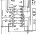
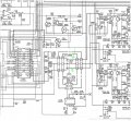
... Can't be absolutely sure, but it looks like the tuner right and left inputs are the fourth pins from the notch end of the chip, one on either side. The output from the tuner is carried through the chip to the third pin on each side, counting from the bottom or opposite end from the notch. What is not clear is if the tape 1 needs to be turned on for the output pins to be activated. Also check the Tape 2 switch, to see what that does.
... It may be that the IC201 output pins, 3rd pins from the bottom, either side, are active when the tuner is turned on, and the Tape switch activations are an option.
OK. I re-checked and it looks like the signals I'm getting are just the outputs from the source applied going into IC201 and my guess is that this IC is not directing the source inputs correctly. I'm not entirely sure as to which pin pairs are the outputs but it looks like it could be the following three sets:

6/23
9/20
12/17

I checked all these pairs with an audio source from both the tuner and an external input and was not able to generate any signal. I also checked these pins when varying the tape selector but no such luck there. It seems clear that signals are entering this IC but not passing through it.
 

Attachments

drc_567

Joined Dec 29, 2008
1,156
... Re-reading abrsvc's post above, it seems that the output should be on the 12/17 pin pair with both Tape switches turned off. So just to check, turn both tape switches off and check the 12/17 pin pair for the tuner signal.
 

Thread Starter

q4#W$7#y

Joined Aug 13, 2020
42
... Re-reading abrsvc's post above, it seems that the output should be on the 12/17 pin pair with both Tape switches turned off. So just to check, turn both tape switches off and check the 12/17 pin pair for the tuner signal.
Confirmed. No signal from 12/17 pair with both tape selectors off.
 

drc_567

Joined Dec 29, 2008
1,156
... Could the tuner signal have jumped to one of the Tape Function pins?
Check pins 6/23 and pins 9/20 to see if there is an audio signal. These pins are like the signal input to the Tape function buttons.
... One more check to see if there is any change: with the power button turned off, unplug the unit power cord for 10 seconds, then plug it back in. Maybe this will reset the CPU controller chip.
 
Last edited:

Thread Starter

q4#W$7#y

Joined Aug 13, 2020
42
... Could the tuner signal have jumped to one of the Tape Function pins?
Check pins 6/23 and pins 9/20 to see if there is an audio signal. These pins are like the signal input to the Tape function buttons.
... One more check to see if there is any change: with the power button turned off, unplug the unit power cord for 10 seconds, then plug it back in. Maybe this will reset the CPU controller chip.
No luck. I re-checked all the output pairs, running through with the following configurations and and observed no signal:

• Only tuner selected
• Tuner and Tape 1 selected
• Tuner and Tape 2 selected

Before this check the unit had been both powered off and unplugged for about an hour.
 

Ylli

Joined Nov 13, 2015
1,092
Double check that you have -16 vdc on pin 1, and +16 vdc on pin 28. All the other pins should show near zero dc.
With the unit on and 'Tuner' selected, you should have audio on pin 4 (L) and pin 25 (R).
You should see the same audio on pin 8 (L) and pin 21 (R). If you do not, it is very likely IC201 is defective.
If you do have audio at pins 8 & 21, as long as 'Tape' is NOT selected, you should also have that same audio on pin 12 (L) and 17 (R). If not, IC201 bad.
 

MrChips

Joined Oct 2, 2009
34,988
I was also going to suggest testing the audio amp output by bypassing IC201.
One problem is we don't know if the volume control IU-2486 is functioning. We don't want to input too large a signal that could blow the amp, or worse, blow your ears.

I would suggest getting and external volume potentiometer (variable pot) and inject the tuner signal via the external pot into the wiper at VR251, either channel. The input to the amp is already AC coupled via C373 and C374.

Check to see if relay RL401 is energized. This enables the amp to speaker output.

If you need clarification just ask.

Denon DRA-545R Volume Control.jpg
 

Thread Starter

q4#W$7#y

Joined Aug 13, 2020
42
Double check that you have -16 vdc on pin 1, and +16 vdc on pin 28. All the other pins should show near zero dc.
With the unit on and 'Tuner' selected, you should have audio on pin 4 (L) and pin 25 (R).
You should see the same audio on pin 8 (L) and pin 21 (R). If you do not, it is very likely IC201 is defective.
If you do have audio at pins 8 & 21, as long as 'Tape' is NOT selected, you should also have that same audio on pin 12 (L) and 17 (R). If not, IC201 bad.
I'll double-check today and confirm voltages for pins 1 and 28.

Update: I re-checked the outputs noted above using the different Tape selections and still no audio. Checking pins one and 28 did confirm roughly +/-16v:

Pin 1: +15.39v
Pin 2: -15.48v
 
Last edited:

Thread Starter

q4#W$7#y

Joined Aug 13, 2020
42
I was also going to suggest testing the audio amp output by bypassing IC201.
One problem is we don't know if the volume control IU-2486 is functioning. We don't want to input too large a signal that could blow the amp, or worse, blow your ears.

I would suggest getting and external volume potentiometer (variable pot) and inject the tuner signal via the external pot into the wiper at VR251, either channel. The input to the amp is already AC coupled via C373 and C374.

Check to see if relay RL401 is energized. This enables the amp to speaker output.

If you need clarification just ask.

View attachment 231148
Thanks. I'm sure I have a spare pot laying around. I'll let you know if I need any further clarification on this but I hope to report back by this evening.
 

MrChips

Joined Oct 2, 2009
34,988
Assuming that the VOLUME control is working, you need to move the level up from 0% position, about 10% should be good enough. Inject an audio signal into R302 at the point shown below. If the VOLUME control is stuck at 0% it will ground out any signal being injected. You can test by measuring the resistance from the point shown to ground. We want the resistance to be greater than 1kΩ (VR251 is 100kΩ).

Denon DRA-545R R302.jpg
 

Thread Starter

q4#W$7#y

Joined Aug 13, 2020
42
Assuming that the VOLUME control is working, you need to move the level up from 0% position, about 10% should be good enough. Inject an audio signal into R302 at the point shown below. If the VOLUME control is stuck at 0% it will ground out any signal being injected. You can test by measuring the resistance from the point shown to ground. We want the resistance to be greater than 1kΩ (VR251 is 100kΩ).

View attachment 231184
OK, I took the measurements at R302 as you suggested and from what I can tell it does look like the VOLUME control is functional. Here are my readings with the volume at three different levels:

0%: 0k
50%: ~28k
100%: ~50k

Additionally I was able to jump a signal from pin four of IC201 to this point and, while the audio is not clear or as loud as expected, the volume does fluctuate with VOLUME knob changes. Testing pin 25 yielded the same result. I'm assuming the lack of clarity and expected volume is due to only passing one signal rather than both. (I experience the same effect when passing the audio from pin 4 or 25 to an external powered speaker, producing weak and muddled audio, but tracing both left and right together produces clear and much louder audio).

Lastly, I'll respond to Ylli's reply separately but voltage readings at pins one and 28 of IC201 yielded roughly +/-16v, respectively.
 

MrChips

Joined Oct 2, 2009
34,988
This points to possibly bad IC201, TC9164N, or bad control signals STB, DATA, CK.
You would need an oscilloscope to check for the presence of control signals.

You may be able to test which input source the selector is stuck on by injecting the audio signal into the correct input pin.

LEFT CHANNEL
2
3
4
5
7
8
9
10
11

RIGHT CHANNEL
27
26
25
24
22
21
20
19
18

You may want to contact @abrsvc as he knows more about this than we do. He says he has TC9164 in stock.
 

Thread Starter

q4#W$7#y

Joined Aug 13, 2020
42
Just posting a final follow-up regarding this.

After installing a new TC9164 the unit is now functioning normally. Everything works as expected and it sounds great. I've been using it every day for the better part of a week with no issues. Big thanks to everyone who contributed to help fix this, I sincerely appreciate your time and expertise.

Just a quick run-down of what I replaced in case anybody with a DRA-545R displaying similar issues stumbles upon this in the future:

Capacitor - C645
Resistor - R432
Transistor - TR417
Analog Switch - TC9164N

Replacing the capacitor fixed my initial issue with the unit not fully powering on. Replacing the last three components resolved the lack of sound.
 
Top