Denon 545R Stereo Receiver - No Speaker output

Thread Starter

hafren

Joined Mar 1, 2019
30
Well I appreciate everyone’s patience and have some progress to report – good & bad. I finally sourced a Toshiba TC9164N (IC201) and soldered it to the board and success as I have amplified sound coming through to the headphones. But I now have significant hum and the unit gets very hot; I’m getting ~130F on the transistors connected to the heat sink.

As mentioned previously when first problem solving the unit I had no signs of overheating so am unclear as to root cause and now have hum. I would appreciate any advice on what I can check next .

I rechecked some voltages as per earlier requests:

Voltage across TP1/TP3 and TP2/TP4 4mV

Rail voltages at TR323 -31.1V and TR321 -31.1V
 

Ylli

Joined Nov 13, 2015
1,092
Looking at the pix of where you had to repair a trace... The trace that the arrow points to is a ground trace, bringing the ground up to IC201. The adjacent traces are the +/- 16 volts supplies, also to IC201. Something must have shorted from one of these to the ground run.

Remove TR413 and do an ohmmeter check on it. Hopefully the excess voltage has not already blown out the new IC201. Let's get the +/- 16 volt lines fixed before we tackle the low +/- 47 volt busses.
 

wayneh

Joined Sep 9, 2010
18,127
Well I appreciate everyone’s patience and have some progress to report – good & bad. I finally sourced a Toshiba TC9164N (IC201) and soldered it to the board and success as I have amplified sound coming through to the headphones.
That's amazing progress! I hope the rest can get straightened out.
 

Thread Starter

hafren

Joined Mar 1, 2019
30
Looking at the pix of where you had to repair a trace... The trace that the arrow points to is a ground trace, bringing the ground up to IC201. The adjacent traces are the +/- 16 volts supplies, also to IC201. Something must have shorted from one of these to the ground run.

Remove TR413 and do an ohmmeter check on it. Hopefully the excess voltage has not already blown out the new IC201. Let's get the +/- 16 volt lines fixed before we tackle the low +/- 47 volt busses.
Removed TR413 and here are the ohmeter results

2.47 k B>C

2.99 k C>B

1.03k B>E

1.02 k E>B

1.98 k C>E

1.41 k E>C

I’m a novice in checking transistors so I tested all three terminals B,C,E in each direction
 

Ylli

Joined Nov 13, 2015
1,092
You used the right pattern. Does your meter have a 'diode' range? If so, try redoing those using the 'diode' range. Based on those number, you have a bad transistor there.
 

Thread Starter

hafren

Joined Mar 1, 2019
30
You used the right pattern. Does your meter have a 'diode' range? If so, try redoing those using the 'diode' range. Based on those number, you have a bad transistor there.
My dmm has a diode setting instruction " Touch the test probes to the diode under test. Forward voltage will indicate 0.4V to 0.7V. Reverse voltage will indicate “1”. Shorted devices will indicate near 0mV. Shorted devices will indicate near 0mV and an open device will indicate “1” in both polarities." results are:
B>C 1.11
C>B 0.586
B>E 0.804
E>B 0.587
C>E 0.482
E>C 0.507
 

Ylli

Joined Nov 13, 2015
1,092
Definitely bad.

Trying to find a replacement for that 2sd2004 transistor. Most of what I am finding is that it is in a TO-92L package, or perhaps an MRT package. Most of the replacements seem to come in larger packages. Does it look like this?:
51JRDpUUmLL._SX425_.jpg
and would there be room for something a little bit bigger?
 

Thread Starter

hafren

Joined Mar 1, 2019
30
Definitely bad.

Trying to find a replacement for that 2sd2004 transistor. Most of what I am finding is that it is in a TO-92L package, or perhaps an MRT package. Most of the replacements seem to come in larger packages. Does it look like this?:
View attachment 177380
and would there be room for something a little bit bigger?
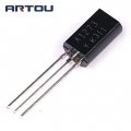
TR413 is a 2SD1913 transistor. Datasheet attached is what I found online and the actual component package is just like datsheet picture
 

Attachments

Ylli

Joined Nov 13, 2015
1,092
OK, I was looking at the wrong schematic version. That should be easier to find a replacement for.
I see some on ebay, but you never know if you are getting the real thing or a counterfeit on ebay. I also see that B&D Enterprises has them, https://www.bdent.com/2sd1913-sanyo-transistor.html. BDent is usually reliable.

I'm tempted to ask you to power it up with TR413 removed and measure the voltage at the point where the base of TR413 connected. Should be about +17 volts. We are confirming the Zener did not get fried. Then also re-measure the rail voltages .. I believe you measured them early in this thread and they were OK, but after the issue with TR413 they were low. A recheck is in order.

If any one else following this thread sees an issue with powering this up for testing purposes without the +16 volt supply, speak now please.
 

Thread Starter

hafren

Joined Mar 1, 2019
30
When you say Zener do you mean D509? Yes when I was originally diagnosing the unit the rail voltages at TR323 and TR321 were -47.8V and 47.7V. Only since I corrected the burned out trace have I seen overheating and after replacing IC201 the rail voltages were lower -31.1V and both –ve??
 

Thread Starter

hafren

Joined Mar 1, 2019
30
OK, I was looking at the wrong schematic version. That should be easier to find a replacement for.
I see some on ebay, but you never know if you are getting the real thing or a counterfeit on ebay. I also see that B&D Enterprises has them, https://www.bdent.com/2sd1913-sanyo-transistor.html. BDent is usually reliable.

I'm tempted to ask you to power it up with TR413 removed and measure the voltage at the point where the base of TR413 connected. Should be about +17 volts. We are confirming the Zener did not get fried. Then also re-measure the rail voltages .. I believe you measured them early in this thread and they were OK, but after the issue with TR413 they were low. A recheck is in order.

If any one else following this thread sees an issue with powering this up for testing purposes without the +16 volt supply, speak now please.
Well I took the risk and powered it up briefly and measured at the board where TR413 base is mounted 16.8V and the rail voltages at TR323 49.1V and TR321 -47.8V.
 

Thread Starter

hafren

Joined Mar 1, 2019
30
I'll go ahead and order a new TR413 from BDent (thanks for this source) but before I do are there any other checks I should perform or components to buy?
 

Thread Starter

hafren

Joined Mar 1, 2019
30
Well I thought I this was finally going to fix it but adding the transistor TR413 (2SD1913) has cured the overheating but I'm just getting distorted sound from the headphones. It also seems like I only get tuner output even after selecting tape in etc.but I am getting amplification when I adjust the volume control. Does this mean I fried the Toshiba TC9164N (IC201) as mentioned earlier (post 24)? Before ordering another IC is there something I can do to verify the IC's bad or check if something else is wrong.

BTW Rail voltages & TR 413/TR417 voltages are all very close to spec.
 

Ylli

Joined Nov 13, 2015
1,092
Well I thought I this was finally going to fix it but adding the transistor TR413 (2SD1913) has cured the overheating but I'm just getting distorted sound from the headphones. It also seems like I only get tuner output even after selecting tape in etc.but I am getting amplification when I adjust the volume control. Does this mean I fried the Toshiba TC9164N (IC201) as mentioned earlier (post 24)? Before ordering another IC is there something I can do to verify the IC's bad or check if something else is wrong.

BTW Rail voltages & TR 413/TR417 voltages are all very close to spec.
Headphone output only? Do you get any output using speakers?

Afraid it does sound like IC201 was blown by the excess voltage and you are going to have to change it again. If you found that socket you mentioned, great - if not, be *extra* careful not to lift any pads when you desolder the old one again. Clipping the pins and desoldering them one-by-one is probably the safest method.

When you have IC201 removed, you can add a couple jumpers from a specific input to the output and see if things work. For example, it you want to use a CD input, add a jumper between pins 3 & 12 and a second jumper between pins 26 & 17. To safeguard the IC pads, would be best to add these jumpers to connected parts rather than the IC pads themselves. For example, instead of using pis 3 & 12 directly add the jumper between the right hand side of R201 and the top of VR201. Do similar for the other jumper. (hopefully the above didn't confuse you - just trying to safeguard those IC pads.)

You could try using those jumpers before removing IC201, but because of the unknown effects of a defective IC201 on the connected circuit, the results could be inconclusive.

That +16 volt line also feeds other circuitry, and that other stuff may also have been damaged. But we'll address those if/when we find them.
 
Last edited:
Top