Delay timer relay control connection problem

Thread Starter

pramodmani

Joined Aug 27, 2017
4
Hi,

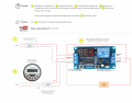
I'm making an automatic fish feeder for my aquarium that'll switch on for 10 seconds every day at a set time to feed the fish.

Attached is the circuit diagram I am using. I have tried to explain everything graphically. I'm not sure where I am doing wrong as this circuit isn't working as it intend to.

There's also an YouTube reference link I have provided.


(from 5:08)

I have taken inspiration from this user and his circuit seems to be working fine. However, his wiring connection is not clear. Can you please help me figure out?
 

Attachments

#12

Joined Nov 30, 2010
18,224
It looks to me like an error on the diagram where +12V is connected to "normally closed". It should be connected to "normally open".
 

Thread Starter

pramodmani

Joined Aug 27, 2017
4
By connecting to normally open, supply will continuously flow to fish feeder and works opposite to what I desire. It cuts off power when the delay timer gets triggered for 10 seconds
 

LesJones

Joined Jan 8, 2017
4,174
I have seen timers on Ebay that look similar to the one you are using. They had quite a few selectable modes of operation and the documentation was not easy to understand. Can you post the information on the timer that you are using. (I am refering to the 12 volt timer with the LED display. Not the mains timer.) I think your problem may be that the timer is not set to behave as you require it to behave.

Les.
 

Thread Starter

pramodmani

Joined Aug 27, 2017
4
Hi Les, I bought it from eBay and it didn't come with any documentation or manual. Learnt to use it from YouTube. This video might also help.


In this video, the center wire (yellow color) is used to trigger the relay timer. What I am looking for is rather than manual triggering, it should happen when the mains timer gets activated and power reaches the trigger line through the 12 volt adaptor.

Attached is the photo of the back side of relay timer. "VCC" is where's the 12 volt main is connected. "IN" is the trigger port.
 

Attachments

LesJones

Joined Jan 8, 2017
4,174
I think your timer is different to the type I thought it was. I think yours only has one mode of operation. I think it just needs a short pulse to trigger it. Try adding this circuit between the power supply that is fed from the mains timer and the trigger input.
Trigger01.jpg

The component values are not critical. The 3k3 resistor is to ensure that the capacitor in the power supply discharges during the time when it's input is off. Almost any diode will do. (1N4148. 1N4001 or any of the 1N400x series) You may have to increase the value of the capacitor if the trigger input requires a reasonably large input current.

Les.
 

Thread Starter

pramodmani

Joined Aug 27, 2017
4
Thanks Les. Yes...you're correct! The relay timer needs a short pulse to trigger it and shouldn't restart for the 1 minute duration it receives supply from the mains timer.

I'll try your solution and get back
 
Top