Deciphering current transformer output waveform problem!

Thread Starter

SiCEngineer

Joined May 22, 2019
442
Hi All,

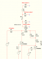
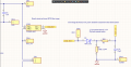
I have a current transformer with 1:100 turns ratio in my fly-back converter. It is designed such that a current of just over 2.5A will trigger a current limit at approximately 3V input to a DSP. I have attached a schematic to this post.

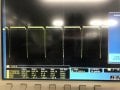
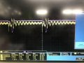
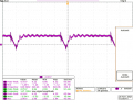
Unfortunately, the output voltage is not at all what I expect. When the switch is off, the voltage is a positive DC signal. When the switch turns on and current flows through the current transformer, the voltage drops right down and often falls below zero and becomes a negative signal. I have also attached an image of the observed waveform, with switching frequency of 650kHz. The CTX is able to operate at 1MHz.

What I would expect is zero DC voltage when the switch is off, and a positive going peak that hits 3V when the switch is on. I was suspicious that I connected the transformer with the wrong polarity, but the waveforms suggests that something else is afoot here.

Does anybody have any suspicions of what may be occuring here? Picture 4 is the current transformer output at the sense resistor.
 

Attachments

ronsimpson

Joined Oct 7, 2019
2,989
For a test please short out the Diode and see what the waveform looks like.
A resistor is normally across a CT. In this case it looks like 120 ohms.
What CT are you useing? Part number? or picture?
 

Thread Starter

SiCEngineer

Joined May 22, 2019
442
The schematic is too small to see.
Sorry! It was direct from oscilloscope and saved as TIF. It hasn't pasted properly. I will attach a word document instead.

My new suspicion is that the diode is only 40V, 0.5A. It seems that there may be more voltage than that developed in the secondary with a 1:100 transformer. I am looking to replace that with an equivalent footprint but 1:50, or to increase the diode voltage maximum.

Diode: PMEG4005EH,115
CTX: CU8965-ALC
 

Attachments

ronsimpson

Joined Oct 7, 2019
2,989
You are using the CT incorrectly. It must see a load. It must see a load that is the same positive and negative. You only have a load in one direction. The core probably is saturated.

If you must have the diode then add two.
1638286907122.png
 

Thread Starter

SiCEngineer

Joined May 22, 2019
442
You are using the CT incorrectly. It must see a load. It must see a load that is the same positive and negative. You only have a load in one direction. The core probably is saturated.

If you must have the diode then add two.
View attachment 253889
Firstly, Ron, thank you very much for the advice. I had the negative terminal of the CTX secondary connected to ground. I have seen it often done like this by the likes of Ray Ridley and never questioned whether it would work. It also works completely fine as in my schematic in LTSpice, but in practice different story entirely.

However, if the current transformer was running into saturation, would you expect to see the waveform that I am? A DC signal when the switch is off? I am quite puzzled as it could definitely be saturation but the waveform does not suggest that is happening. But certainly could be the case.

How come with a standard fly-back transformer, you can use a single diode rectifier, but with a fly-back CTX you cannot? Do the same principles not apply?
 

crutschow

Joined Mar 14, 2008
34,285
It also works completely fine as in my schematic in LTSpice, but in practice different story entirely.
That's because the ideal transformers in LTspice don't saturate.
How come with a standard fly-back transformer, you can use a single diode rectifier, but with a fly-back CTX you cannot? Do the same principles not apply?
The same principles apply for core saturation, but the design is different.
A fly-back transformer is designed to not saturate the core with its rated DC current.
A CTX is designed to carry only an AC waveform with no significant DC component (similar to any AC transformer).
 
Last edited:

ronsimpson

Joined Oct 7, 2019
2,989
Lets look at a CT in a different way.
120 ohm resistor on the secondary in one direction and infinity in the other direction.
100:1 turn ration and 10,000:1 impedance ration
The primary will look like 0.012 ohms in one direction and open in the other direction. (not good)
(you are running the CT at almost it highest frequency .... OK but maybe not) Again, what part number?
When a CT is used correctly current gets moved form P to S by the turn ration. So 1A becomes 0.01A on the 120 ohm resistor.
When there is no resistor the primary is open and a large voltage is on the primary and a 100x larger voltage is on the secondary. The (Voltage * Time) on the transformer is very large and the core saturates. After saturation the inductance heads down near zero and the voltage drops. No current flows in the secondary.

Do you know if the core can handle 3V on the secondary?
 

Thread Starter

SiCEngineer

Joined May 22, 2019
442
Lets look at a CT in a different way.
120 ohm resistor on the secondary in one direction and infinity in the other direction.
100:1 turn ration and 10,000:1 impedance ration
The primary will look like 0.012 ohms in one direction and open in the other direction. (not good)
(you are running the CT at almost it highest frequency .... OK but maybe not) Again, what part number?
When a CT is used correctly current gets moved form P to S by the turn ration. So 1A becomes 0.01A on the 120 ohm resistor.
When there is no resistor the primary is open and a large voltage is on the primary and a 100x larger voltage is on the secondary. The (Voltage * Time) on the transformer is very large and the core saturates. After saturation the inductance heads down near zero and the voltage drops. No current flows in the secondary.

Do you know if the core can handle 3V on the secondary?
Interesting stuff, thanks again. Also thanks to Crutschow regarding LTSpice transformers not saturating - that is fairly obvious but something I completely neglected to think about.

I mentioned the part number above - it is a CU8965-ALC from Coilcraft, data sheet here: CU8965-ALC Coilcraft | Mouser United Kingdom. It is designed for ADP1051 Datasheet and Product Info | Analog Devices. You can see that they use the same circuit as me for current sensing. So the saturation must be occuring due to DC current in the primary or excessive voltage? This is 1:50 from Coilcraft, same series, same footprint: cst7030-1100725.pdf (mouser.co.uk). Maybe worthwhile replacing my 1:100 part with this and seeing if there is a difference?

I did verify that the volt-seconds were suitable for the application. Would replacing this with their 1:50 version rather than 1:100, and replacing the resistor with a smaller value help things at all? The 1:50 version has 1/2 the value of VuSec product, so I don't think it changes much!

PS: I have another converter in parallel with this, using the same 1:100 transformer, but at 200-400kHz rather than 600kHz+. The waveform is fine, and shape is as I expect. Is there a way to solve this without re-designing the PCB? You mentioned something about "if I need a diode", could it work without one, at all? Just thinking out loud. I do have a current limited power supply - maybe I can put a tiny bit of current into the converter and ramp it up and see if I can see the current transformer saturate? Anything wrong w/ this approach? I have often seen engineers place a 10Kohm resistance in parallel straight after the CTX to ground, would this make any difference to the function of the circuit? It seems to help quite a bit in the LTSpice simulation.
 

Attachments

Last edited:

Thread Starter

SiCEngineer

Joined May 22, 2019
442
Interesting stuff, thanks again. Also thanks to Crutschow regarding LTSpice transformers not saturating - that is fairly obvious but something I completely neglected to think about.

I mentioned the part number above - it is a CU8965-ALC from Coilcraft, data sheet here: CU8965-ALC Coilcraft | Mouser United Kingdom. It is designed for ADP1051 Datasheet and Product Info | Analog Devices. You can see that they use the same circuit as me for current sensing. So the saturation must be occuring due to DC current in the primary or excessive voltage? This is 1:50 from Coilcraft, same series, same footprint: cst7030-1100725.pdf (mouser.co.uk). Maybe worthwhile replacing my 1:100 part with this and seeing if there is a difference?

I did verify that the volt-seconds were suitable for the application. Would replacing this with their 1:50 version rather than 1:100, and replacing the resistor with a smaller value help things at all? The 1:50 version has 1/2 the value of VuSec product, so I don't think it changes much!

PS: I have another converter in parallel with this, using the same 1:100 transformer, but at 200-400kHz rather than 600kHz+. The waveform is fine, and shape is as I expect. Is there a way to solve this without re-designing the PCB? You mentioned something about "if I need a diode", could it work without one, at all? Just thinking out loud. I do have a current limited power supply - maybe I can put a tiny bit of current into the converter and ramp it up and see if I can see the current transformer saturate? Anything wrong w/ this approach?
Here is an image from the above test where I reduced the input current limit right down towards zero. As you can see the issue persists but the amplitude is reduced. I have also included now a screenshot of the secondary current transformer voltage to ground - before the diode but without the current limit. It is higher than expected. I am slightly confused why it also saturates even at such low input current where the secondary voltage is substantially less than this - suggesting that it must be DC current of the fly-back causing the saturation of the core, even just a small amount of DC current pushing it beyond the 2000 Gauss that is recommended.

Does this indicate that the source of saturation for the core is DC current rather than the voltage developed on the core, volt-seconds etc? Had to take a photo with my phone since oscilloscope decided to not recognise my USB - sorry!
 

Attachments

Last edited:

Thread Starter

SiCEngineer

Joined May 22, 2019
442
Here is an image from the above test where I reduced the input current limit right down towards zero. As you can see the issue persists but the amplitude is reduced. I have also included now a screenshot of the secondary current transformer voltage to ground - before the diode but without the current limit. It is higher than expected. I am slightly confused why it also saturates even at such low input current where the secondary voltage is substantially less than this - suggesting that it must be DC current of the fly-back causing the saturation of the core, even just a small amount of DC current pushing it beyond the 2000 Gauss that is recommended.

Does this indicate that the source of saturation for the core is DC current rather than the voltage developed on the core, volt-seconds etc? Had to take a photo with my phone since oscilloscope decided to not recognise my USB - sorry!
And, finally, here is the primary voltage across the current transformer. I measured this with a large loop because it is differential mode probe. Therefore it could have some additional noise induced in the loop. However, again not exactly what I expect from the CTX! Probably shows there may be more wrong than just the saturation of the core. If it helps, I have also included an image which shows the primary and secondary voltages imposed on one another to see more clearly what is happening with the primary voltage.

Again, any recommendations moving forward are welcomed.
 

Attachments

Last edited:

michael8

Joined Jan 11, 2015
410
See the ADP1051 datasheet page 23 figure 25 for the correct primary current sense circuit. They show a resistor directly acrros the curent transformer output and then the diode/resistor stuff...
 

ronsimpson

Joined Oct 7, 2019
2,989
Circuit in #14, The resistor across the coil is 100 or 120 ohms. This is the resistor to measure current.
Then the diode.
Now the 10k or 1k resistor. This resistor is only to pull "CS1" to ground.
Do not do post #9.

I looked at the CU8965 data sheet. It will do 3V for 10uS before saturation. Then the core needs to be reset. When I look at the scope pictures the voltage is there a long time.

It looks like most of us agree the "burden resistor" needs to be across the transformer.
 
Last edited:

Thread Starter

SiCEngineer

Joined May 22, 2019
442
What is the current transformer primary current waveform?
As my circuit currently stands I have no way of measuring this. I did not put a current sense resistor in the circuit (in retrospect, a mistake). Since I have two converters in parallel, I did place a 3-pin high current connector between the input voltage and each converter, so I could quite easily solder a 10mOhm through hole resistor between that and sense the input current, but this still won't be the actual current flowing in the current transformer, but instead the input current before the resonant capacitor. Maybe that could at least give an "idea" of the current. I have attached a schematic of the primary circuit of the fly-back. I have attached a schematic. The current transformer is placed where it currently is in my circuit, resistor is where I propose that I can measure current.
 

Attachments

Thread Starter

SiCEngineer

Joined May 22, 2019
442
Circuit in #14, The resistor across the coil is 100 or 120 ohms. This is the resistor to measure current.
Then the diode.
Now the 10k or 1k resistor. This resistor is only to pull "CS1" to ground.
Do not do post #9.

I looked at the CU8965 data sheet. It will do 3V for 10uS before saturation. Then the core needs to be reset. When I look at the scope pictures the voltage is there a long time.

It looks like most of us agree the "burden resistor" needs to be across the transformer.
Hi Ron,

Just double checking - do you propose that the burden resistor (120R for 1:100) be placed across the CTX secondary, directly), and that the diode follows that, followed by 10Kohm pull down and then the filter. As the attached photo shows? If this would solve the problem, how? If the problem is the CTX is not reset, how does that additional resistor achieve reset?

3V for 10uS seems like quite a time, especially considering my switching frequency is so high. Anyway, I can solder a 120R resistor across the test pins, and replace the 0805 120R resistor with a 10K one quite easily to test this hypothesis, if we agree that could help things.
 

Attachments

crutschow

Joined Mar 14, 2008
34,285
I suggest the connection below.
It removes the D1 diode forward drop from the output voltage (since the transformer output is a current).
D2 provides a path for the return current.

1638464142325.png
 

Thread Starter

SiCEngineer

Joined May 22, 2019
442
Hi Ron,

Just double checking - do you propose that the burden resistor (120R for 1:100) be placed across the CTX secondary, directly), and that the diode follows that, followed by 10Kohm pull down and then the filter. As the attached photo shows? If this would solve the problem, how? If the problem is the CTX is not reset, how does that additional resistor achieve reset?

3V for 10uS seems like quite a time, especially considering my switching frequency is so high. Anyway, I can solder a 120R resistor across the test pins, and replace the 0805 120R resistor with a 10K one quite easily to test this hypothesis, if we agree that could help things.
I suggest the connection below.
It removes the D1 diode forward drop from the output voltage (since the transformer output is a current).
D2 provides a path for the return current.

View attachment 254082
Very interesting, I will give this a go. I tried with the additional 10K burden resistor to no avail. Will update this post when I get the result. Thanks a bunch for the help!

Note: Just added the extra diode in the configuration you've suggested and the large voltage across the secondary has been completely attenuated, instead of 50V+ it is less than 5V... Looks like this is the solution! So the addition of this extra diode allow a path for the "return" current, and thus allows transformer reset and thus avoids transformer saturation. Do I have that right?
 

Thread Starter

SiCEngineer

Joined May 22, 2019
442
You are using the CT incorrectly. It must see a load. It must see a load that is the same positive and negative. You only have a load in one direction. The core probably is saturated.

If you must have the diode then add two.
View attachment 253889
Hi Ron,

I also notice now that this circuit is same as what Crutschow provided. I actually completely read the diagram wrong when you sent it originally and therefore it did not help the simulation. I apologise and must thank you also for this reply as it most likely is the solution.
Side note: is the resistor necessary? If it is for current limiting I'd expect that would already be taken care of elsewhere in the circuit. I plan to solder a through hole Schottky diode between TP18 and TP19 so it would just make things a little easier on the soldering side.

Thank you for your help in this matter, it is appreciated!
 
Top