 Facebook
 Google
 GitHub
 Linkedin
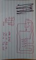
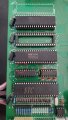
Yes, the owner wants it back sooner than later. He realizes that I am on vacation (last day today), but wants it on line ASAP. The whole scope thing is a learning curve for me, so I'll be watching some You-tube tutorials.The board looks clean from our perspective.
I would hold off on doing any cleaning or pulling chips for now.
I would prefer to wait until we see some oscilloscope waveforms.
Is there any rush on this repair job?
Dead Dinosaur (animatronic).
- Thread starter v-8 volvo
- Start date


| Thread starter | Similar threads | Forum | Replies | Date |
|---|---|---|---|---|
|
|
DEAD gell cell baTTERY restoration ? | Power Electronics | 2 | |
|
|
Froze dead car battery. | Off-Topic | 5 | |
| T | Ups line interactive “battery mode” dead, tested good batteries | Power Electronics | 0 | |
|
|
Is "Giveaways" dead? | Feedback and Suggestions | 2 | |
|
|
Espresso machine power supply dead ( Q0365R PWM) | General Electronics Chat | 10 |


