Dead Dinosaur (animatronic).

Thread Starter

v-8 volvo

Joined Mar 29, 2011
41
Regarding the gunk between the 373 and 8255 chips, that cleaned up with the deoxit.
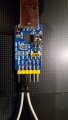
OK, now I'm getting the same results with TX, RX and GND disconnected!
So obviously the serial/TTL adapter isn't seeing the UART.
20230723_134724.jpg
The adapter was connected to the serial port RX to RX, TX to TX, etc.
 
Last edited by a moderator:

djsfantasi

Joined Apr 11, 2010
9,237
The adapter was connected to the serial port RX to RX, TX to TX, etc.
What’s your reasoning for doing it this way. I would connect TX (sensor) to RX (board). And vicey versey.

You transmit some data on the TX pin. The receiving board looks for the data on the receiving (RX) pin.
 

JohnInTX

Joined Jun 26, 2012
4,787
What’s your reasoning for doing it this way. I would connect TX (sensor) to RX (board). And vicey versey.
You transmit some data on the TX pin. The receiving board looks for the data on the receiving (RX) pin.
+1

First, disconnect those wires shown in the photo in #41 and connect TXD to RXD on that blue USB-RS232 board itself (nothing connected to the dinosaur yet). Any characters typed should be shown on the terminal screen. If not visit the terminal setup and set handshaking to NONE (not RTS/CTS or XON/XOFF). Select FULL DUPLEX so that only characters received by the terminal are displayed.

When you get that far you can connect further down the line until you have the entire circuit working and communicating:
Terminal TXD -> DB9 Pin 3 -> MAX 232 RX232 input (Pin 9 or 14) -- MAX232 TTL output (10 or 13) ->UART RX (Pin 10) -> jumper at socket -> UART TX (Pin 11)-> MAX232 TTL Input (Pin 11 or 12) -- MAX232 RS232 Output(Pin 8 or 15) -> DB9 Pin 2 -> Terminal RXD; DB9 pin 5 connected to Terminal GND.

Note that the DB-9M in post #32 is the terminal connector (DTE). The DB-9F on the dino should be wired as DCE with the pins noted in bold here so that the terminal TX connects to the dino RX and the dino TX connects to the terminal's RX as noted in the quote.
 
Last edited:

JohnInTX

Joined Jun 26, 2012
4,787
That is not a USB to RS232 board. It is USB to TTL. RS232 has up to ±15V. He has likely damaged the board by putting incorrect voltages on it.
Ouch. I was looking at the DIP switch which implies 232 if I read it right. But TS needs to verify for sure, I really don't know.
 

Thread Starter

v-8 volvo

Joined Mar 29, 2011
41
Ouch. I was looking at the DIP switch which implies 232 if I read it right. But TS needs to verify for sure, I really don't know.
Just to verify: On the 2 position DIP, 1 is set to ON, for USB. 2 is off
The slide switch below the DIP is set to 232-TTL, instead of 232-485.
I looped TX to RX on same board and entered text on terminal program. Whatever I typed displayed in Blue. After hitting return, same text appeared in green, under the blue text.
Based on the blue board settings, am I screwed? I feel sick to my stomach after all of this.
 

Attachments

Thread Starter

v-8 volvo

Joined Mar 29, 2011
41
No worries. The worst that can happen is you will get double characters as you type.

We're kind of getting ahead of ourselves. Have we determined that the processor is running?
Not yet. I thought that using the terminal was one of the tools to use for the processor diagnosis. I need to put this away for the night. Thank you all and good night.
 

JohnInTX

Joined Jun 26, 2012
4,787
Not yet. I thought that using the terminal was one of the tools to use for the processor diagnosis.
It is but after you have checked the easy stuff. Keep in mind that for all of the good advice posted here about establishing a serial link, it's dependent on the assumption that 1)there is one and 2)that we can derive how it works. It's all good info but buzz out the simple stuff first. Nothing matters if the processor is not running. You can poke that out using the techniques outlined above.

Had a great night myself with the g'kids. Good night.
 

Thread Starter

v-8 volvo

Joined Mar 29, 2011
41
It is but after you have checked the easy stuff. Keep in mind that for all of the good advice posted here about establishing a serial link, it's dependent on the assumption that 1)there is one and 2)that we can derive how it works. It's all good info but buzz out the simple stuff first. Nothing matters if the processor is not running. You can poke that out using the techniques outlined above.

Had a great night myself with the g'kids. Good night.

John,
Could you please elaborate on verifying processor operation with the DMM?
 

JohnInTX

Joined Jun 26, 2012
4,787
The first order is to see if the processor is running and executing code.

The DMM can provide some quick, very rough information - usually. Not all circuits are compatible with these hacks so take all at face value.
Ground is pin 20 of the processor. All measurements are referred to that.

RST Pin 9: RST must be low for the processor to run.
EA Pin 9: Must be high to execute code from internal program ROM
ALE Pin 30: ALE pulses when the 8255s are accessed to do IO operations. It also may pulse constantly on each program memory access unless that has been turned off by the software. The DMM will likely show a fluctuating reading if ALE is toggling.
XTAL2 Pin 18: With the DMM set to AC mode, it should show some flucuating voltage readings between the power supply rails. If the reading is stable at 0 or Vcc, that might indicate that the oscillator is not running.
P2.0 to P2.7 pins 21-28: Some of these appear to be outputs. If the voltage is floating without the chip installed then a good logic 0 when the chip is present, that would suggest that the program at least got started and initialized the ports.

The scope is your friend here though. The scope setup in post #28 is pretty close to what you need to buzz out the processor IO bus:
VERTICAL:
CHAN A V/Div=.2 (this will be 2V/Div with the 10X probe)
DC Coupling (as shown in the photo)
DISPLAY = A
TRIGGER = A
None of the tan buttons pressed.

HORIZ DISPLAY:
AUTO (for now)
5 us / DIV

MAIN TRIGGER:
NEG
No HIGH/LOW Reject
DC Coupling
INT(ernal)
No EXT/10

Adjust for a trace on the center line.

Connect the probe ground to a known DC ground - verify continuity to pin 20 (GND) of the processor.
OSCILLATOR:
Put the tip of the probe on XTAL2 (Pin 18) You should get a blurred signal a couple of divisions high if the oscillator is running.
Rotate the trigger level control until the display stabilizes.
Rotate the TIME/DIV towards .2uS / Div. If the oscillator is running you should see roughly a sine wave at about 11 MHZ (90nS period).
You might have to change the trigger coupling to AC but it should work.

ALE
Select 2uS / DIV and AUTO trigger
Probe ALE, you should get at least an irregular, probably blurred signal swinging between 0 and Vcc.
Adjust the trigger level as before to try to stabilize the display.
Change from AUTO to NORM trigger on ALE. You might have to mess with the trigger level.

Gotta go.
Good luck!
 

Thread Starter

v-8 volvo

Joined Mar 29, 2011
41
The first order is to see if the processor is running and executing code.

The DMM can provide some quick, very rough information - usually. Not all circuits are compatible with these hacks so take all at face value.
Ground is pin 20 of the processor. All measurements are referred to that.

RST Pin 9: RST must be low for the processor to run.
EA Pin 9: Must be high to execute code from internal program ROM
ALE Pin 30: ALE pulses when the 8255s are accessed to do IO operations. It also may pulse constantly on each program memory access unless that has been turned off by the software. The DMM will likely show a fluctuating reading if ALE is toggling.
XTAL2 Pin 18: With the DMM set to AC mode, it should show some flucuating voltage readings between the power supply rails. If the reading is stable at 0 or Vcc, that might indicate that the oscillator is not running.
P2.0 to P2.7 pins 21-28: Some of these appear to be outputs. If the voltage is floating without the chip installed then a good logic 0 when the chip is present, that would suggest that the program at least got started and initialized the ports.

The scope is your friend here though. The scope setup in post #28 is pretty close to what you need to buzz out the processor IO bus:
VERTICAL:
CHAN A V/Div=.2 (this will be 2V/Div with the 10X probe)
DC Coupling (as shown in the photo)
DISPLAY = A
TRIGGER = A
None of the tan buttons pressed.

HORIZ DISPLAY:
AUTO (for now)
5 us / DIV

MAIN TRIGGER:
NEG
No HIGH/LOW Reject
DC Coupling
INT(ernal)
No EXT/10

Adjust for a trace on the center line.

Connect the probe ground to a known DC ground - verify continuity to pin 20 (GND) of the processor.
OSCILLATOR:
Put the tip of the probe on XTAL2 (Pin 18) You should get a blurred signal a couple of divisions high if the oscillator is running.
Rotate the trigger level control until the display stabilizes.
Rotate the TIME/DIV towards .2uS / Div. If the oscillator is running you should see roughly a sine wave at about 11 MHZ (90nS period).
You might have to change the trigger coupling to AC but it should work.

ALE
Select 2uS / DIV and AUTO trigger
Probe ALE, you should get at least an irregular, probably blurred signal swinging between 0 and Vcc.
Adjust the trigger level as before to try to stabilize the display.
Change from AUTO to NORM trigger on ALE. You might have to mess with the trigger level.

Gotta go.
Good luck!
Using the DMM:
RST Pin 9: .2mV
EA Pin 9: I don't follow
ALE Pin 30: 1.8 V No pulse
XTAL Pin 18: Decreases from 110mV slowly. When 9mV is reached, voltage drops sharply to 0V.
P2.0-2.7 Pins 21-28: All 5.28V
DMM set to DCV for everything but XTAL check.
Done for the night. Will break out the scope tomorrow.
 
Top