Facebook
 Google
 GitHub
 Linkedin
Hi Folks!
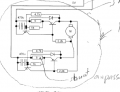
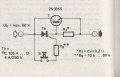
Looking for a simple current limiter for a 12V dc gear motor. Normal current ca 40 mA. When current rises the circuit should shut off and remain off.
Shut off about 150 mA.
The motor drives a grain feeder, a spiral rotating inside a tube, rotating 2-4 revolutions every 20 seconds. But it can be stopped by unwanted things passing through and stop it, the current rises and motor stalls and finally it burns or cracks. Like putting a bar in a bicycle wheel.
Some transistors and current raising over a resistor, voltage falls?, and the transistsors switches of somehow? I also need a signal going out to a Raspbarry Pi computer giving it a High status on a GPIO pin telling the motor stoped.
Some have an idea how to disign this circuit?
Thank You
(English is not my first language, retired technichs and math and electronics teacher in Sweden)