DCM/CCM analysis problem

Thread Starter

LeoT

Joined Jan 16, 2019
16
Hi!
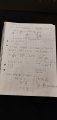
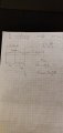
I don't know if this is the right place to post or ask but I am stuck in a university course problem that seems really simple but I can't get my head around it. Can anyone give me tips on how to start and go forwards with the problem and possible answer for it? I want to learn it, not one fast answer. I have drawn the circuit and read through material about CCM/DCM and it seems easy but I don't get how this is so hard. Thank you in advance.
 

Attachments

Thread Starter

LeoT

Joined Jan 16, 2019
16
So how you define the DCM and CCM ?
DCM: "Occurs because switching ripple in inductor current or capacitor voltage causes polarity of applied switch current or voltage to reverse, such that the current- or voltage-unidirectional assumptions made in realizing the switch are violated." This sentence starts to become a little language barrier for me. I'm Finnish.

"The CCM mode is such that the inductor current has to different derivatives or slopes within the switching cycle." This also but not so much.
I try to understand these sentences better from graphic presentation but it is hard
 

Jony130

Joined Feb 17, 2009
5,598
To be honest I totally don't understand your definition.

Continuous Current Mode (CCM) means that current through inductor flows continuously throughout the switching period (always >0).
ΔIon = ΔIoff

Discontinuous Current Mode (DCM) means that current through inductor reaches zero before the end of the switching period (when switch is OFF)

https://forum.allaboutcircuits.com/threads/smps-experiment-problem.73116/#post-512842

https://forum.allaboutcircuits.com/threads/buck-converter-problem.145072/#post-1231833
 

Thread Starter

LeoT

Joined Jan 16, 2019
16
To be honest I totally don't understand your definition.

Continuous Current Mode (CCM) means that current through inductor flows continuously throughout the switching period (always >0).
ΔIon = ΔIoff

Discontinuous Current Mode (DCM) means that current through inductor reaches zero before the end of the switching period (when switch is OFF)

https://forum.allaboutcircuits.com/threads/smps-experiment-problem.73116/#post-512842

https://forum.allaboutcircuits.com/threads/buck-converter-problem.145072/#post-1231833
That sounds really simple, I understood that from graphs where it showed the voltage on-time and off-time slopes + the time when inductor current is zero in DCM. From the problems starting values I should compute the resistance first? Don't know how and then the K = 2L/RTs to get the voltage going in?
 

Jony130

Joined Feb 17, 2009
5,598
Here you have the tip

The situation at the boundary between the CCM and DCM will look like this:

12a.png

Where :
VL - voltage across the incutor.
IL - inductor current
I_lout - output (load) current equal to the average value of the inductor current IL.

And this
https://forum.allaboutcircuits.com/...lator-theory-of-operation.113526/#post-883379

And this is all you need to find the solution You do not have to even bother to use your K factor equation.
Simply understand the basics they are really simple.
 

Thread Starter

LeoT

Joined Jan 16, 2019
16
Thank you for all the help so quickly, still trying to work this.
Edit: I can't solve this...:(
 
Last edited:

Thread Starter

LeoT

Joined Jan 16, 2019
16
If I understood it correctly, the circuit operates always in CCM with the given Vin values and only in DCM when Pout=10 W and Vin=<29,23 V? Why is it outside the given Vin values. And why isn't there anything mentioned about Iout??
 

Jony130

Joined Feb 17, 2009
5,598
If I understood it correctly, the circuit operates always in CCM with the given Vin values and only in DCM when Pout=10 W
I disagree with this conclusion.

For Vin = 35V and Vo = 28V in CCM mode the duty cycle is equal to:
D = Vo/Vin = 28V/35V = 0.8,

Hence at the boundary (see post #11) the inductor current will rise to:

ΔIL = VL/L *Δt = (35V - 28V)/22μH * 0.8*1/75kHz = 3.394A

And because of a fact that at the boundary between CCM and DCM the inductor current is rising from 0A and ends at 3.394A.
So the load current is equal to 3.394A/2 = 1.697A (load current is equal to the average value of the inductor current)

RL = 28V/1.697A = 16.5Ω and the power is 28V*1.697A = 47.5W

As you can see any load current smaller than 1.7A will bring the converter into DCM mode (any RL > 16.5Ω).

On the other hand for Vin = 70V the duty cycle is 28V/70V = 0.4 (in CCM)

Therefore the minimum load current needed if we want to stay in CCM mode is equal to:

ΔIL = VL/L *Δt = (70V - 28V)/22μH * 0.4*1/75kHz = 10.18A --->IL = 10.18A/2 = 5.09A

Which correspond to the output power equal to 28V*5.09A = 142.52W

And this means that conwerter will work in CCM mode only if Po ≥ 142.5W
 
Top