DC to AC conversion via Bubba oscilator

Thread Starter

Stefan Zlatev

Joined Jun 5, 2015
4
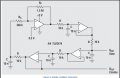
Greetings everyone! I built a "Bubba oscilator" circuit, which is supposed to convert DC signal into AC. (Resource: http://www.hscott.net/bubba.pdf ) The uploaded picture is the exact schematic that I built with only 1 modification. We did not have the TLV2474 ( http://www.ti.com/product/tlv2474 ) so I used 2xTLV272 instead ( http://www.ti.com/product/tlv272 ). When I first tested it the osciloscope showed a perfect sine wave output, but after my initial excitement passed I noticed that the sinewave actually has no negative values. It moves between approximately 200mV and 700mV. My question is: Can the different op amp be the reason for that? Or is there something entirely different I am missing?
PS: I will upload a screenshot of the osciloscope with the exact values about 30 minutes later.
Thank you in advance!
 

Attachments

Bordodynov

Joined May 20, 2015
3,181
To have your picture drawn by 0.5 V.
Need to understand this is not like a 0.5V.
You have to understand how 0.5VCC =0.5*5V=2.5V.
This is done most easily resistive divider
(two resistors to 10 kohm).
 

OBW0549

Joined Mar 2, 2015
3,566
When I first tested it the osciloscope showed a perfect sine wave output, but after my initial excitement passed I noticed that the sinewave actually has no negative values. It moves between approximately 200mV and 700mV. My question is: Can the different op amp be the reason for that? Or is there something entirely different I am missing?
Why would you expect the sine wave outputs of your circuit to have any negative values? Your circuit operates from only a positive power supply, so the outputs are constrained to between zero volts and +5 volts.
 

Thread Starter

Stefan Zlatev

Joined Jun 5, 2015
4
Why would you expect the sine wave outputs of your circuit to have any negative values? Your circuit operates from only a positive power supply, so the outputs are constrained to between zero volts and +5 volts.
So what will happen if I add a second supply of -5 volts on another op amp?
 

OBW0549

Joined Mar 2, 2015
3,566
So what will happen if I add a second supply of -5 volts on another op amp?
If you want outputs from this circuit that go both (+) and (-), you need to power all four opamps from positive and negative supplies, such as +/-5V. Also, if you want the outputs to be symmetrical about zero volts (or as close to symmetrical as possible), connect the non-inverting input of the upper left-hand opamp to ground rather than to +0.5V.
 

Thread Starter

Stefan Zlatev

Joined Jun 5, 2015
4
If you want outputs from this circuit that go both (+) and (-), you need to power all four opamps from positive and negative supplies, such as +/-5V. Also, if you want the outputs to be symmetrical about zero volts (or as close to symmetrical as possible), connect the non-inverting input of the upper left-hand opamp to ground rather than to +0.5V.
Thank you!!
 

ramancini8

Joined Jul 18, 2012
473
I am the original designer of the Bubba Oscillator, and a few things got mixed up when the circuit was copied (without giving me credit). The first stage non-inverting gain is 5.16, so the bias voltage should be 0.484V to obtain a dc output voltage of 2.5V (center of the supply range). A bias voltage of 0.5V should suffice for most cases, but the output dc voltage will be 2.588V. The load seen by the output should be high impedance and carefully protected because it is also connected to a oscillator op amp input. An op amp input is ideal to couple into, and If you want an ac output with a swing around ground, capacitor coupling into something like 10M gives it to you without the need for a second supply.
 

Thread Starter

Stefan Zlatev

Joined Jun 5, 2015
4
Would you please explain to me a part of the calculations.
If w0(omega) =1/RC that is 1/(10^4 * 10^-8) = 10^4 or 10k
Then how does that fit into the gain equation which is 1/(sqrt(1^2 + (w/w0)^2) ?
 

crutschow

Joined Mar 14, 2008
34,470
If you want outputs from this circuit that go both (+) and (-), you need to power all four opamps from positive and negative supplies, such as +/-5V. Also, if you want the outputs to be symmetrical about zero volts (or as close to symmetrical as possible), connect the non-inverting input of the upper left-hand opamp to ground rather than to +0.5V.
You can also couple the output from a single-supply circuit through a capacitor to a grounded resistor.
That will give a signal exactly centered around ground with equal plus and minus peaks.
 

ramancini8

Joined Jul 18, 2012
473
I had a dog named Bubba who constantly chased his tail and I was watching him tirelessly chasing his tail when I got the idea for the circuit, thus the name Bubba.

For Stephan: the circuit oscillates where the feedback equals -180 degrees, and each section give -45 degrees phase shift, so four sections yield an oscillator. Beware, the bandwidth of the op amp much be high enough so the op amp phase shift is small at the oscillation frequency or frequency errors occur.

The theoretical gain works out to be 4, but to insure operation with normal component tolerances it is boosted up to 5.16. Higher gain insure oscillation but it introduces distortion. Try reading "Op Amps for Everyone" where all this is explained in detail; the book is free on the Texas Instruments web site.
 

AnalogKid

Joined Aug 1, 2013
11,056
My beard is the same color as yours. For those around here of fewer years, know this:

Ron Mancini is one of the few long-term analog design gurus. His technical prowess, insight, creativity, and communication skills have inspired and coached decades of circuit and system designers.

ak
 

#12

Joined Nov 30, 2010
18,224
For those around here of fewer years, know this:

Ron Mancini is one of the long-term analog design gurus, whose insight, creativity, and communication skills have inspired and coached decades of circuit and system designers.

ak
I know. I am one of the herd he taught, but I still can't grow a beard. :(
 
Top