Dc power line communication

Thread Starter

bug13

Joined Feb 13, 2012
2,002
Hi guys

I have this problem, the following circuit work great until the power line was replaced with a longer cable, my first thought was the source and load impedance is mismatched, and some kind of signal reflection is happening. But I have no idea what is happening as I have no/little knowledge of this area.

So my question are:
- what cause it?
- how do I fix it?

When is working:
local send a signal to remote unit, remote unit flash a led at ~1Hz

When is not working: (after a new cable is installed)
local send a signal to remote unit, remote unit flash a led at odd rate, it's more like a normal 1Hz + a short pulse between two or three normal 1Hz

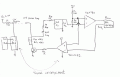
circuit: (updated, error on the original one)
 
Last edited:

THE_RB

Joined Feb 11, 2008
5,438
Why is the lower comparator +input connected to the other signal, not the fixed Vreference? Is that just a schematic error?
 

Thread Starter

bug13

Joined Feb 13, 2012
2,002
Why is the lower comparator +input connected to the other signal, not the fixed Vreference? Is that just a schematic error?
There is actually an error, the two 100k divider/+input of the top opamp is connected to between R14 and R15, I will update the circuit when I get home.

edit:

Now the circuit is updated, any thought?? As I have no clue.
 
Last edited:

ScottWang

Joined Aug 23, 2012
7,505
Try to Reducing R17(470),R45(470),R15(1K).
Before you change the value, you should measure the amplitude of voltage of 12V power line of right side, after you changed them then measure again.
 

ScottWang

Joined Aug 23, 2012
7,505
Could you explain why?
I rechecked the value of resistors, I think they should be increasing R17(470),R45(470), and reducing R15(1K).
Why : I just thought if the impedance of cable was increased then the amplitude of voltage will be lower, so if change the value of resistors may changing the amplitude of voltage, if the amplitude too low may not enough capable to drive the TLC2272, and also can't drive the pic.
When you tried it then tell me what will it be?
 

Thread Starter

bug13

Joined Feb 13, 2012
2,002
For whoever still follow, the problem is from the cable, I tried a different cable but same length, problem solved.

But be a bad cable, but this bad cable work on other device, just not this one
 

THE_RB

Joined Feb 11, 2008
5,438
There is actually an error, the two 100k divider/+input of the top opamp is connected to between R14 and R15, I will update the circuit when I get home.

edit:

Now the circuit is updated, any thought?? As I have no clue.
Is that the only bug? Why is the +input of the bottom opamp connected to the signal going into the top opamp?

Isn't the top opamp the receiver, and the bottom one the transmitter? If so, the +input of the bottom opamp should be connected to the 1/2Vdd reference, which is the midpoint of R11 and R12.

And the wire you added from that point back to R14 is probably wrong too.

Or maybe I am misunderstanding what the bottom opamp is supposed to do?
 

Thread Starter

bug13

Joined Feb 13, 2012
2,002
Is that the only bug? Why is the +input of the bottom opamp connected to the signal going into the top opamp?

Isn't the top opamp the receiver, and the bottom one the transmitter? If so, the +input of the bottom opamp should be connected to the 1/2Vdd reference, which is the midpoint of R11 and R12.

And the wire you added from that point back to R14 is probably wrong too.

Or maybe I am misunderstanding what the bottom opamp is supposed to do?
I don't know, it could be some errors from the schematic. I knowledge is not enough to tell if there is errors or not, I just copied it as it is.
 

THE_RB

Joined Feb 11, 2008
5,438
I don't know, it could be some errors from the schematic. I knowledge is not enough to tell if there is errors or not, I just copied it as it is.
Can you say that the circuit is supposed to be a transmitter and receiver?

If so, then we can be sure the top opamp is the receiver, and the bottom one is the transmitter. Both should have their + input connected to 1/2 Vdd (mid point between R11 and R12).

I have coreected the schematic and attached it below. It should work now. :)
 

Attachments

Top