DC motor controller project

Thread Starter

Xavier Pacheco Paulino

Joined Oct 21, 2015
728
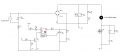
Previously I asked some questions regarding motor control. Well, I'm actually working on designing one by myself, specifically a motor control for treadmill. The purpose of this post is to update what I have done so you can throw your 2 cents and give suggestions. I attach an schematic of what I have so far. I'm now selecting a proper mosfet and a gate driver. As recommended in a previous post, I plan to use the IXFH80N25X3. Datasheet: https://www.mouser.com/ds/2/205/DS100753B(IXFA-FP-FH-FQ80N25X3)-1113848.pdf I thought of using parallel MOSFETs, but this one seems to stand my ratings so I don't see the need to use two mosfets (so two snubbers ?) and increase project complexity.

And this gate driver sounds good: http://www.ixysic.com/home/pdfs.nsf/www/IXD_609.pdf/$file/IXD_609.pdf

As you can see, I'm now trying to design the power stage. I will use PWM @25 kHz from an STM32 MCU. Also, I will sense motor's current using the LTS 25-NP sensor.
 

Attachments

MaxHeadRoom

Joined Jul 18, 2013
30,654
What is the reason for the two control loops?
One varying the DC supply and the other the Mosfet?
Or is this the supply inrush controller you mentioned?
Max.
 

Thread Starter

Xavier Pacheco Paulino

Joined Oct 21, 2015
728
What is the reason for the two control loops?
One varying the DC supply and the other the Mosfet?
Or is this the supply inrush controller you mentioned?
Max.
What do you mean by "two control loops"?

Yes, in a previous post I talked about the supply inrush. It was a circuit made using relay, so I changed to a triac circuit to switch the power to the motor.
 

MaxHeadRoom

Joined Jul 18, 2013
30,654
I realized that what you have the triac circuit for.
There is also a fairly common method where a DC motor is controlled this way with a triac before the bridge, no mosfet is used, but it is not such smooth a control as PWM.
Max.
 

Thread Starter

Xavier Pacheco Paulino

Joined Oct 21, 2015
728
I'm trying to simulate this circuit using Proteus, but the behavior is unpredictable. That is, Proteus throws me a lot of simulation errors. Do you know a better simulation software?
 

Bordodynov

Joined May 20, 2015
3,431
First about the shortcomings of your scheme.The first circuit (on TRIAC) can only turn your motor on and off.
I would remove R7, C4 and connect the cathode of the diode to the second motor terminal (i.e., in parallel). But it's up to you.
I recommend LTspice.This program is free.You just need to add my collection of models.See:
https://forum.allaboutcircuits.com/...nents-models-of-ltspice-free-download.133690/
See my alternative scheme #21:
https://forum.allaboutcircuits.com/...in-ac-dimmer-circuit-using-optocoupler.67875/
I have a PWM control of 1kHz.It is necessary to use your supply voltage and the resistance and inductance of the motor to calculate the circuit.The motor at me is modeled inductance with internal parasitic parameters (LTspice uses more perfect models of inductances and capacitors).If you are interested, I will upload my schema in LTspice format.My collection contains many models of triacs, diodes, optocouplers and transistors.
 

Thread Starter

Xavier Pacheco Paulino

Joined Oct 21, 2015
728
First about the shortcomings of your scheme.The first circuit (on TRIAC) can only turn your motor on and off.
I would remove R7, C4 and connect the cathode of the diode to the second motor terminal (i.e., in parallel). But it's up to you.
I recommend LTspice.This program is free.You just need to add my collection of models.See:
https://forum.allaboutcircuits.com/...nents-models-of-ltspice-free-download.133690/
See my alternative scheme #21:
https://forum.allaboutcircuits.com/...in-ac-dimmer-circuit-using-optocoupler.67875/
I have a PWM control of 1kHz.It is necessary to use your supply voltage and the resistance and inductance of the motor to calculate the circuit.The motor at me is modeled inductance with internal parasitic parameters (LTspice uses more perfect models of inductances and capacitors).If you are interested, I will upload my schema in LTspice format.My collection contains many models of triacs, diodes, optocouplers and transistors.
Thank you. The purpose of the triac circuit is just that, to enable the power to the motor (and probably reducing the effect of inrush current by using zero crossing). The circuit across the mosfet is intended as an snubber network.
 

be80be

Joined Jul 5, 2008
2,395
Simulating is good but there has to be a reason there been bread boards so long !
I like working thing's out on Qucs then testing on the bread board.

Some stuff needs a PCB to really see how well it works.
 
Top