Darlington transistor pair design

Thread Starter

rogerthatpsr

Joined Aug 22, 2006
19
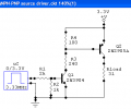
I wanted some help in designing Darlington transistor pair... application is : i should use it in one of the microcontroller's output port to basically source more current.... i have VCC=3.3v... current drawn frm darlington can be around few uA n output can be around 50 to 100mA... how do i proceed ? also should i put base to emitter resistor ?
 

SgtWookie

Joined Jul 17, 2007
22,230
I wanted some help in designing Darlington transistor pair... application is : I should use it in one of the microcontroller's output port to basically source more current....
OK, you say "source more current" - did you mean "source more current", or "sink more current"?

Keep in mind that there are ICs available that contain multiple Darlington channels (4, 7, and 8); most of them are designed to sink current, but some can source current.
A couple of common examples are the ULN2003N and ULN2803N (designed to sink current)

I have VCC=3.3v... current drawn frm darlington can be around few uA n output can be around 50 to 100mA... how do i proceed? also should i put base to emitter resistor?
You are really better off to purchase pre-made Darlington transistors or transistor arrays. You will wind up spending much less time and money, and the result will be much more satisfactory.

One big disadvantage of a Darlington is the Vce; with a 100mA load, you may see a Vcd of 1v to 1.5v. This can result in significant power dissipation in the transistor.

There are logic level MOSFETs available that avoid that problem altogether.
 
Last edited:

Thread Starter

rogerthatpsr

Joined Aug 22, 2006
19
Yes it is "source more current "... i want to use it on a output port to drive load..(require about 100 mA minimum) above is a mass production design so inorder to keep the cost low n make it simple, i wanna stickon to discrete transistor version. i need little help about design n to choose proper value resistors.... it is required to transmit only logic data (eg:0101000111 ) which says drarlington pair should operate as a simple switch....
 

MaxSmoke

Joined Oct 29, 2009
35
SgtWookie is right when he states the at eh VCE drop will be at least 1V0 if not 1V5. Can you post a schematic showing how you are using the Darlington pair, as the above NPN Darlington pair would be better at sink current than sourcing.

Also, You might like to consider what happens when the load fails short circuit, i.e. what protection are you providing for the output transistor.
 

Wendy

Joined Mar 24, 2008
23,421
MOSFETs only drawback is their gate voltage. The digital versions absolutely require at least 5V to turn fully on, while most of the rest require 10V on the gate. Once these conditions are met, however, they are much more conductive, and do not draw any gate current other than a short surge when the state is changing. Many times they are interchangeable with regular transistors, although the theory of operation is totally different.

Another BJT transistor configuration I learned about on this forum is the Sziklai Pair, which has the same advantages of a Darlington (high gain), but drops a bit less voltage CE and only 0.6 BE.
 

SgtWookie

Joined Jul 17, 2007
22,230
OK, if you need to source current, then you should probably use an NPN-PNP pair.

What will be the bit data rate? If it's gong to be a high rate, you may run into problems with transistor saturation recovery times.
 

Thread Starter

rogerthatpsr

Joined Aug 22, 2006
19
will this thing work? any changes to be made for resistor values ? is that 10k resistor necessary or is it ok to leave the pin open so tat current flows through the external load only when a pin A of microcontroller goes high( external ground n internal ground are common)
 

Attachments

Wendy

Joined Mar 24, 2008
23,421
You have a pullup resistor of 100Ω. This is a pretty hefty load for a µC, are you sure you want that small a resistor?

The 10KΩ is probably a good idea. It will provide bias for the transistor if the load isn't present.
 

SgtWookie

Joined Jul 17, 2007
22,230
Darn, I did this simulation and then forgot to post it. :rolleyes:

Better late than never... here it is:


R1 limits the base current of Q1.
R2 helps Q1 turn off quickly when the output of the uC goes low.

R3 limits the base current of Q2.
R4 helps Q2 turn off quickly when Q1 turns off.
RLoad represents your 100mA output load.

It simulates reliably at 3.33MHz, but I wouldn't push it much higher than that.
 

Attachments

SgtWookie

Joined Jul 17, 2007
22,230
Well, I'm afraid that the way you had the driver configured originally, it would've blown the lid right off the uC. :eek:

LOTS of current flow.

I re-vamped it a bit, it seems to work pretty well now:


It needed the 100 Ohm resistor bumped up to 120 Ohms, and moved over to the collector of Q1.

Q1 needed a base current limiting resistor; that's where your biggest problem was.

The output will source 100mA OK, but you'll lose a volt due to the Darlington configuration. Also, if you don't have a decent load on it (at most 1k) the waveform won't look so hot.
 

Attachments

Thread Starter

rogerthatpsr

Joined Aug 22, 2006
19
@ SgtWookie and Bill_Marsden Thank you very much for the help... problem is i knew only the theory part of the above transistor config... din no how to calculate resistor values... searched on net but it din'nt help.... so how do u decide resistor values ? any link to simple transistor design resources ??


Thanks once again
 

lihle

Joined Apr 12, 2009
83
its simple what you can do is to calculated the value of RB (base resistor) then connect a relay at the collector so that when the output of the microcontroller is 3.3v it will first turn on the darligton pair.(the available ic TIP-110). then the collector current will turn on the relay and your external circuit will work.
 

Wendy

Joined Mar 24, 2008
23,421
I don't know the specs to your processor, but if you have to have that resistor I would start high (10KΩ), then go down.

I learned my transistor theory from a book called Malveno's Transistors, and 30 years experience. My advice is keep asking questions, and don't be afraid to build experimental circuits (and occasionally smoking them).

There are a lot of good resources on the web, the local textbook (links on top of this page) has a pretty good section on transistors, but nothing beats experience and experimentation.
 

SgtWookie

Joined Jul 17, 2007
22,230
Well, to drive a 100mA load, the base of Q2 needs about 10mA current.
R4 will pass about 6mA current. That means Q1's base needs at least 1.6mA current.

I went for a bit of overkill; about 2.6mA. [eta] I knew that some overkill would be necessary, as Q2 would need a pull-up resistor for cutoff.

Vbe of Q1 figured around 0.7, 3.3 Vcc, so (3.3-0.7)/2.6mA = 1k for the base current limiting resistor.

R4 had to be fairly low to turn off Q2 quickly. I just started with the 100 Ohms, and adjusted it a bit after looking at the simulation.

Your mileage may vary, but it's a good starting point.
 
Last edited:

Thread Starter

rogerthatpsr

Joined Aug 22, 2006
19
i use orcad capture to draw schematics... but is there any simple n very user friendly simulation software to analyze voltages n currents at different parts of circuit, so that i can understand them better....

and some books from the starting pg deal with derivations n formulas.. in some transistor books u turn pages n it'll be full of maths.....i'll be like " oh my god " !!:) do v have to remember all those derivations or should v be in a position to derive all that at any given time from the scratch ?? or is it ok if v no the basic concepts n how it works ??? i'm really confused......
 

Wendy

Joined Mar 24, 2008
23,421
Yep, math is a part of electronics. You must understand Ohm's Law, to know what voltages and currents to expect. Other than that it isn't so bad, start with the job you're wanting to do, then look for configurations on how to do it.

If you have a specific project this group will help, just post what you're wanting to do.
 

SgtWookie

Joined Jul 17, 2007
22,230
i use orcad capture to draw schematics... but is there any simple n very user friendly simulation software to analyze voltages n currents at different parts of circuit, so that i can understand them better....
Well, there are quite a number of SPICE simulation packages out there. Orcad has SPICE built-in. I haven't used it, but it's my understanding that Orcad is one of the better packages.

The problem with simulating in one software package, and then transferring it to Orcad, is that you'll wind up doing everything twice. In a small circuit consisting of just a few components, that's not a really big deal. However, small circuits tend to grow pretty quickly.

Then there's always a chance that you'll make a mistake or typographical error while entering the schematic back into Orcad, and you'll wind up having a non-functional circuit.

and some books from the starting pg deal with derivations n formulas.. in some transistor books u turn pages n it'll be full of maths.....i'll be like " oh my god " !!:) do v have to remember all those derivations or should v be in a position to derive all that at any given time from the scratch ?? or is it ok if v no the basic concepts n how it works ??? i'm really confused......
Well, you really do need to know at least the basics. Our online E-books can help you a great deal with that.

Also, getting something to work in a SPICE simulation isn't an absolute guarantee that it will work the same way using real components. The simulation will help you narrow in on a workable solution, but you really have to build it to verify that your SPICE model was a good one.
 
Top