Darlington pair shorting in communist amp

gerty

Joined Aug 30, 2007
1,305
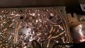
Solder side of the board, near the end of the blue wire, there appears to be a through hole possibly with a missing component. Other side of the board, between the ends of the red wires, the solder appears to be awful thick and in globs, possibly shorting to adjacent pads.
 

Thread Starter

nikolatesla

Joined Sep 5, 2015
17
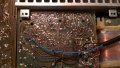
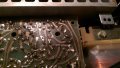
There was some working around before, the wires connecting the transistors were all worn out so I changed them (hence the different colours). The DC bridge has 3 new diodes as they aren't really the same so I guess there was once a problem with it. Some circuit was burnt and replaced with wire. Around the excess flux in the first transistors in darlington configuration the circuit is kinda worn out, sticking off the pcb. I am considering printing another pcb and remaking it from scratch.
 
Last edited:

Thread Starter

nikolatesla

Joined Sep 5, 2015
17
I tried rubbing alcohol and the toothbrush, it didn't really work as I expected, the black stuff is burnt flux and it won't come off. I guess this isn't even flux, it's some sort of resin, similar to pine resin, back in the commie years they used it alot
 

Attachments

Thread Starter

nikolatesla

Joined Sep 5, 2015
17
Solder side of the board, near the end of the blue wire, there appears to be a through hole possibly with a missing component. Other side of the board, between the ends of the red wires, the solder appears to be awful thick and in globs, possibly shorting to adjacent pads.
The hole was like that, it is for another way to connect the blue wire, the channel with the blue wire is working properly. Also, the place you pointed out with the red wires is part of the good channel, the problem seems to be on the other half of the pcb.
 

Kermit2

Joined Feb 5, 2010
4,159
If you can get your hands on some turpentine, a little bit will soften up pine resin if left on over night. Then some gentle scrapping with a small screwdriver or similar and most of that stuff can then be removed with the toothbrush.
Have you checked resistance between your heatsink and ground? Between your heat sink and your transformer secondary, and transformer chassis? Lots of comparison readings between identical places on both channels ? There will be a place where resistance should be much lower than working channel compares. Let's find them and go back to the schematic to look at those places. You may need to replace your components to do this thoroughly.
 

Thread Starter

nikolatesla

Joined Sep 5, 2015
17
I can't get ahold of turpentine, so I will try just rubbing off somehow. The resistance bewteen the heatsink and ground is 0.01, same goes for tranformer chassis and heat sink. In the photos I provided there was a screw on the heatsink, that is the common point where the chassis ground, heatsink and pcb grounding meet via 2 cables. I will remove all the capacitors because they mess up my measurements, but first I will try to measure voltage and current on both channels on the transistor mounting pins, just to be sure, that IF, only IF the device will work long enough to measure, giving the fact that I only have one 630mA fuse left and where I am now we don't have a proper electronics shop.
 

Kermit2

Joined Feb 5, 2010
4,159
At this point voltages don't really matter and we know current is to large by the blown fuse. Comparing resistance readings between channels is what you need to do. It's up to you to get it done. If you feel you've checked it before then verify it again and check something else. It is hiding somewhere uncommon so check something you don't think could be it.
 

Thread Starter

nikolatesla

Joined Sep 5, 2015
17
I removed all the capacitors and measured resistances between transistor pin holders and ground and between them. Values were approximatedly the same, with variations of about 0.2, with readings on the 2000k mode. Upon removal a 47 pF capacitor broke in two in my hands, though it was from the good channel. They seem unreliable. I will do again the measurements, just to be sure
 

Thread Starter

nikolatesla

Joined Sep 5, 2015
17
Here are the values of the measurements:
Left channel (faulty):
T415: BE is 001, BC is 1 (no conductance whatsoever), EC is 1 after capacitor charging.
T409: BE is 002, BC is 003, CE is 004.
T417: BE is 001, BC is 1 after capacitor charging, CE is 1.
Right channel (working):
T416: BE is 001, BC is 007, CE is 011.
T410: BE is 002, BC is 003, EC is 004.
T418: BE is 001, BC is 1 after capacitor loading, EC is 1.
All these values were obtained while measuring on the 2000kohm with a multimeter with the mentioned transistors removed (i measured between their mounting pins) and all capacitors in the amp circuit and the 2x4700uF capacitors removed. I guess the capacitor charging occuring during measurements is due to caps in preamp circuit or a capacitor on the transformer circuit.
 

Thread Starter

nikolatesla

Joined Sep 5, 2015
17
I inspected the resitors around T416-T410 pair and T415-T411 pair (R434, R430, R429 and R433). The resistances are showing correct values, also, checking T410 and T411 they seemed okay. Any toughts?
 
Top