 Facebook
 Google
 GitHub
 Linkedin
Hi all,
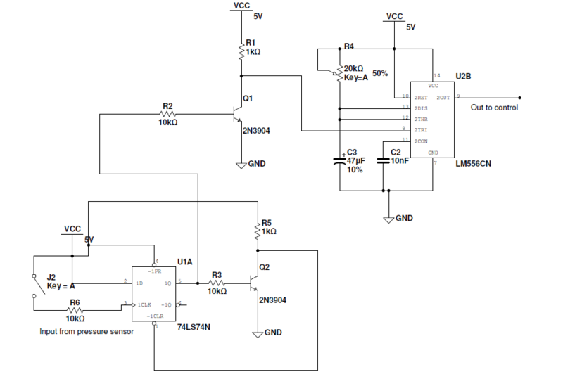
I have a 7474 positive edge triggered flip flop. At power up, I have the D input, ~PRE, and ~CLR all tied high. I need an initial low on the ouput Q. The output Q is high upon power up. The function of this circuit is to detect a positive edge that causes the output to go high and then quickly reset itself resulting in a glich that triggers the 556 timer. This event should happen on every positive edge on the clock input. How can I configure this to have an initial low at power up? The 10k resistor on the clock input is not in the circuit.
I have a 7474 positive edge triggered flip flop. At power up, I have the D input, ~PRE, and ~CLR all tied high. I need an initial low on the ouput Q. The output Q is high upon power up. The function of this circuit is to detect a positive edge that causes the output to go high and then quickly reset itself resulting in a glich that triggers the 556 timer. This event should happen on every positive edge on the clock input. How can I configure this to have an initial low at power up? The 10k resistor on the clock input is not in the circuit.

Last edited:


