Facebook
 Google
 GitHub
 Linkedin
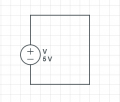
Now I think this method will not work in all cases. If we connect an ideal source (no internal resistance) with an ideal wire.Ok, I did review.
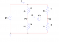
You can find a solution by inserting a resistance R between the two nodes.
Then work out the answer as R approaches the limit of zero ohms.
I have to run now so I can't do the calculation.
Someone please do this.
In order to calculate current flows through the ideal wire I use the limit:
\(I = \lim_{R \rightarrow 0} \frac{V}{R} = \propto \)
This means that when R very very small, almost zero, I will be infinity but it is still indeterminate at R = 0, right?
Attachments
-
 5.1 KB Views: 46