
I will be building a tightly insulated house soon. Because of this, when I turn on exhaust fans I will need to introduce make-up air into the house.
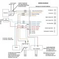
I purchased a Fantec system model MUAS750. This system will energize and introduce additional air into the house when a signal is received on the controller pins. I've attached a wiring diagram.
It appears that the controller needs a 5V signal produced by a current sensor (Greystone model CS-650-10) to turn on the system which then opens the damper and energizes the fan. The current sensor is to monitor a power lead to the kitchen exhaust fan. My problem is that I need to monitor at least 3 different fans. These fans could all be turned on simultaneously but if that happens, I believe the current sensor would output much more than 5V.
A couple issues:
1.) I am testing the sensor on a small fan (Fantec model RVF4). When I turn the fan on I am only seeing .2V output from the sensor. I need 5V. I will try wrapping a couple turns of the line or neutral line in hopes it will output close to 5V.
2.) I need to monitor multiple fans but there is only one input on the controller. Is it possible to parallel multiple current sensors into the inputs on the controller? Or maybe I can run the line or neutral line from ALL fans through one current sensor and "clamp" the voltage with a Zener? Maybe some sort of logic device already exists for this purpose?
Please help.
Attachments
-
 67 KB Views: 13


