Current sense circuit

Thread Starter

pinkyponky

Joined Nov 28, 2019
351
Hi all,

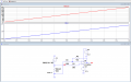
I'm need to measure the current from 100uA to 20A, for that I have design the circuit by using the differential amplifier. As I know the operation of this amplifier is to amplifying the differential signal which is present at the input stage. But, according to my circuit (which is attached below), I designed the circuit with gain=1 even though the output voltage of the amplifier is double. Please can you see the circuit and let me know If I did any mistakes?.
 

Attachments

BobTPH

Joined Jun 5, 2013
8,813
I'm need to measure the current from 100uA to 20A, for
Good luck with that. That is a range if 200000:1. Meters do this by using different ranges. If a single circuit has to cover that range, you will have a hell of a time keeping the noise at the low end bellow the signal,

Bob
 
Last edited:

dcbingaman

Joined Jun 30, 2021
1,065
You are using high side monitoring. So the inputs are sitting at 50V on both legs. Way outside of normal operation. Here is an updated one with the fix. You also should have some RC filtering (I did not add it here) to get rid of any high frequency noise. I have three outputs, multiplying by 10, 100, and 1000 to deal with the large range of currents you are trying to measure. Even so, to measure 100uA you are going to need a larger value sense resistor, at 0.001 ohms that is only 100 nanovolts! You cannot amplify something that small.
 

Attachments

Thread Starter

pinkyponky

Joined Nov 28, 2019
351
Already, I have read that tutorial, There are two R1's and R2's, I was confusing that which R1 and R2 need to be applied in that formula?.

Is that always V1 voltage to be considered that is connecting to the non-inverting terminal?. On other hand, the V2 voltage to the inverting terminal?.

Because so other tutorials says that VOUT = R2 / R1 (V2 – V1).
 

Thread Starter

pinkyponky

Joined Nov 28, 2019
351
hi pp,
You could try this option.
E

Added asc with Current Source
Why you have added 2.49ohms before the shunt resistor, and more over the amplifier you used is not a differential amplifier, because one resistor is missing which is connect to the input of the non-inverting amplifier. I don't know Im right or wrong just asking.
 

ericgibbs

Joined Jan 29, 2010
18,766
hi pp,
The 2.49R was added for Test only, it limits the 50Vdc voltage source current to 20A, which is your maximum measurement value.
In my 2nd circuit I used a Ramped 0A to 20A Current source, so no 2.49R required.

As the Rshunt resistor in my circuit has one end connected to 0V, there is no need for a differential amplifier. So the 10k to the INV input of the OPA is connected to 0V.

You are always right to ask, if in doubt.;)

E
 

Thread Starter

pinkyponky

Joined Nov 28, 2019
351
hi pp,
The 2.49R was added for Test only, it limits the 50Vdc voltage source current to 20A, which is your maximum measurement value.
In my 2nd circuit I used a Ramped 0A to 20A Current source, so no 2.49R required.

As the Rshunt resistor in my circuit has one end connected to 0V, there is no need for a differential amplifier. So the 10k to the INV input of the OPA is connected to 0V.

You are always right to ask, if in doubt.;)

E
Ok..

But, I'm using the circuit for high side monitoring, not low side. So, the both inputs should connect to the voltage which is across shunt resistor?.

So, If I use your circuit, then I can't measure on the high side, according to my understanding.

I asked already, why my circuit is not working. You said that my circuit doesn't have high Common Mode voltages on that OPA input. What does it mean?. How can I improve that in my circuit.

Please, can you explain clearly. I think your circuit does not work.
 

ericgibbs

Joined Jan 29, 2010
18,766
I asked already, why my circuit is not working. You said that my circuit doesn't have high Common Mode voltages on that OPA input. What does it mean?. How can I improve that in my circuit.
hi,
With a Vsupply of only +/-2.5V the datasheet, states that the highest pemissable voltage on the INV and NINV inputs is Vsupply -1.3V.
On your circuit the NINV input has +25V and the end of R1 is at +50v.

These voltages far exceed the stated voltage limits, in a real circuit the OPA would just blow!!

If you want to measure high side currents you must choose an OPA that can tolerate these high input voltages, also usually the OPA would also require a high supply voltage.

Do you have details of the actual Project application to post.?
E
 

Thread Starter

pinkyponky

Joined Nov 28, 2019
351
[/QUOTE]
On your circuit the NINV input has +25V and the end of R1 is at +50v.
[/QUOTE]
Where do I need to measure to know the value of the common-mode voltage?. I think that we need to measure just before the IN and NIN terminals?. Am I right?. If not, please can you explain this?.

[/QUOTE]
These voltages far exceed the stated voltage limits, in a real circuit the OPA would just blow!!
[/QUOTE]
Do you mean that, I have a 25V at the NIN terminal and the datasheet is stated that VCM=V-1.3, where V as 2.5V, So VCM=1.2V according to the datasheet. So, in my circuit VCM=25V and datasheet stated VCM=1.2V. This what you stated in the above sentence. Please can you give me the clarity?.
 
Top