Current Regulation at 400 VDC

Thread Starter

Spacky

Joined Jul 11, 2020
7
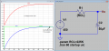
Need to slowly charge large voltage capacitors - typically 20 - 50 uf @ 450 VDC. Problem is that as the capacitor charges, it requires a larger applied voltage to continue charging at an effective rate. Need a design for current limiter for this application - probably limiting charge current to a couple of mA.
 

Papabravo

Joined Feb 24, 2006
21,157
A supply of 450V will not be able to charge your capacitors to 450 VDC. It will get arbitrarily close and the closer it gets the longer it will take to get closer. You do not need a current limiter since the capacitor essentially does that for you in conjunction with a resistor. Let's say you want to limit the charging current to 2 mA. for the 50uF part. A 225KΩ resistor will do that, but it will take more than five RC time constants to get close to your goal. It will be at 99.326% of your goal, or 446.97 VDC. That will be just under a minute. Will that work for you?
 

Thread Starter

Spacky

Joined Jul 11, 2020
7
A supply of 450V will not be able to charge your capacitors to 450 VDC. It will get arbitrarily close and the closer it gets the longer it will take to get closer. You do not need a current limiter since the capacitor essentially does that for you in conjunction with a resistor. Let's say you want to limit the charging current to 2 mA. for the 50uF part. A 225KΩ resistor will do that, but it will take more than five RC time constants to get close to your goal. It will be at 99.326% of your goal, or 446.97 VDC. That will be just under a minute. Will that work for you?
Really appreciate your response. I have, however, been through this discussion with a number of radio techs (like myself) who use various manually-regulated applied voltage and charge rates. (not appealing) I thought it would be possible to get some smart electronic device to do the regulation for me but can't find a circuit for this high voltage. And nope, you can't charge a new 50 uF capacitor to 447 volts in just under a minute. You could if it were one that had been in service but these are new and need to be "formed" before you can apply 450 volts. (New ones and used ones that have been sitting around a long time do not have the aluminum oxide layer built up to withstand that potential). These are well known issues in the industry and these values seem specific to vacuum tube radios and similar equipment but the problem persists. I still believe there must be a circuit that would do the job of babysitting the charge process as the capacitor requires regularly increasing the voltage at it's terminals to continue charging over a period of time (hours). Thanks again. If anything comes to mind I'm all ears.
 

Papabravo

Joined Feb 24, 2006
21,157
Really appreciate your response. I have, however, been through this discussion with a number of radio techs (like myself) who use various manually-regulated applied voltage and charge rates. (not appealing) I thought it would be possible to get some smart electronic device to do the regulation for me but can't find a circuit for this high voltage. And nope, you can't charge a new 50 uF capacitor to 447 volts in just under a minute. You could if it were one that had been in service but these are new and need to be "formed" before you can apply 450 volts. (New ones and used ones that have been sitting around a long time do not have the aluminum oxide layer built up to withstand that potential). These are well known issues in the industry and these values seem specific to vacuum tube radios and similar equipment but the problem persists. I still believe there must be a circuit that would do the job of babysitting the charge process as the capacitor requires regularly increasing the voltage at it's terminals to continue charging over a period of time (hours). Thanks again. If anything comes to mind I'm all ears.
Your math and physics are obviously different than mine. So good luck with your rockets.

Sure looks to me like I can do what I said. Just checking is 56+ seconds less than 1 minute?
 

Attachments

Last edited:

crutschow

Joined Mar 14, 2008
34,280
If you really need a constant-current circuit, below is the LTspice simulation of one using two transistors that generates a constant-current charge of about 2mA.
The current is ≈0.6V divided by R1.

I didn't have any high voltage MOSFET models, so you would have to find a 500V rated device for the M1 P-MOSFET.
(Although the model in the simulation doesn't show a breakdown, in a real circuit it would).

The Zener protects both Q1's collector-emitter voltage, and M1's gate-source voltage from excess voltage, clamping it at about 12V.

1623719754955.png
 
Last edited:

Papabravo

Joined Feb 24, 2006
21,157
The problem is the TS did not describe precisely what his requirements were. He said he wanted to slowly charge...with a current limiter using a couple of milliamps. He did not mention constant current, but that's as good a way to do it as there is albeit with a few more components. I'm thinking he wants to take longer, but maybe I'm reading more into it than he actually meant. I'm not sure about the "forming" mumbo jumbo, I've never heard of it and I had tube receivers and transmitters back in the 60s and 70s and we never bothered with such stuff. We also had great big blue caps of 330,000 uFd. on our +5V supplies for the original power hungry TTL computers we built. One of our "radio techs" welded a screwdriver to the terminals by using it to do a fast discharge. Geeez...what a mess.
 
Last edited:

crutschow

Joined Mar 14, 2008
34,280
Please check my work ........
A possible problem is that unmatched FETs can have a large difference in threshold voltage, which can mess up the current-mirror operation.
Might be better to use BJTs which generally have only a small difference in their base-emitter voltages at a given current.
 

LowQCab

Joined Nov 6, 2012
4,022
True, but there's a very wide adjustment range,
and I'm guessing that Spacky will be monitoring the Current going into the Test-Capacitor,
and adjusting the Current to suit his purposes with the 10-turn Pot,
and then leaving it to charge.

Also, a Trim-Pot and a couple of load Resistors on the Gates would allow
dialing-out any discrepancies in Threshold-Voltages, if necessary.
Maybe I'll add them in just for extra insurance.

He didn't specify anything about possibly limiting the Voltage at the Capacitor,
just that he was using a ~450V Supply,
that kinda leaves that question hanging.
.
.
.
 

Thread Starter

Spacky

Joined Jul 11, 2020
7
Your math and physics are obviously different than mine. So good luck with your rockets.

Sure looks to me like I can do what I said. Just checking is 56+ seconds less than 1 minute?
Your math looks right to me - I just want to charge over 6 hours or so and be able to increase the voltage as it charges so that the current remains fairly constant. At any rate, I really do appreciate your feedback and thanks for taking the time.
 

Thread Starter

Spacky

Joined Jul 11, 2020
7
If you really need a constant-current circuit, below is the LTspice simulation of one using two transistors that generates a constant-current charge of about 2mA.
The current is ≈0.6V divided by R1.

I didn't have any high voltage MOSFET models, so you would have to find a 500V rated device for the M1 P-MOSFET.
(Although the model in the simulation doesn't show a breakdown, in a real circuit it would).

The Zener protects both Q1's collector-emitter voltage, and M1's gate-source voltage from excess voltage, clamping it at about 12V.

View attachment 241308
Excellent! thanks very much. I'll see if I can scare up the components, put on my protective gear and give it a go. :cool: I assume it will still perform well with only a 20 uF cap?
 

MrSalts

Joined Apr 2, 2020
2,767
Your math looks right to me - I just want to charge over 6 hours or so and be able to increase the voltage as it charges so that the current remains fairly constant. At any rate, I really do appreciate your feedback and thanks for taking the time.
Charging a cap at a constant current results in a "perfectly" linear voltage ramp. Charging/discharging a cap with a constant current is how one makes a triangle wave. So, I'd recommend @crutschow 's circuit.
 

Thread Starter

Spacky

Joined Jul 11, 2020
7
The problem is the TS did not describe precisely what his requirements were. He said he wanted to slowly charge...with a current limiter using a couple of milliamps. He did not mention constant current, but that's as god a way to do it as there is albeit with a few more components. I'm thinking he wants to take longer, but maybe I'm reading more into it than he actually meant. I'm not sure about the "forming" mumbo jumbo, I've never heard of it and I had tube receivers and transmitters back in the 60s and 70s and we never bothered with such stuff. We also had great big blue caps of 330,000 uFd. on our +5V supplies for the original power hungry TTL computers we built. One of our "radio techs" welded a screwdriver to the terminals by using it to do a fast discharge. Geeez...what a mess.
Once again, I sincerely appreciate all the responses - very helpful and I think I'm now ready to implement a couple of the ideas in an effort to continue my education. Regarding "forming" See https://www.tdpri.com/threads/do-new-electrolytics-need-to-be-formed.318636/ and the info from CoolBlueGlow March 20, 2012.
 
Top