Current reference from bandgap voltage with oscillator

Thread Starter

analog_design255

Joined Dec 13, 2024
1
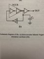
I want to build a relaxation oscillator like the schematic but I should have to use a bandgap reference voltage to create a stable current for the charge and discharge of the capacitor.
I want to use a Schmitt trigger and a feedback path which consists of two inverters. What does it mean with VCCS (Voltage controlled current source?). Are these two inverter the place where I can put the current which was produced by the bandgap voltage reference?
And how can I build a current mirror with the bandgap voltage reference to create the reference constant current? I want to build all in 0.18um CMOS technology.
 

Attachments

crutschow

Joined Mar 14, 2008
38,322
One way to generate both a charge and discharge constant current is to use two complimentary current mirrors, one with PMOS transistors and one with NMOS transistors.
With a little clever circuit design you should be able to use one bandgap reference for both mirrors.
 

MisterBill2

Joined Jan 23, 2018
27,186
Another interesting scheme would be to use a single constant current regulator as the operating voltage source for the inverter charging and discharging the capacitor.
 

Ian0

Joined Aug 7, 2020
13,097
You could have a constant current sink which runs all the time, and a switchable constant current source of twice the value.
When the switchable source is OFF the circuit sinks current I discharging C, when it is ON it sources 2I of which the sink sinks I, leaving I to charge C.

Alternatively, would a Howland current pump do the job?
 

MisterBill2

Joined Jan 23, 2018
27,186
Really, a CMOS gate is often fairly symetrical. At least some of them are. AND, WHY the stable current source?? Is that to hold a constant frequency?? or some other reason.
 

sparky 1

Joined Nov 3, 2018
1,218
The results are only as good as the equipment used to measure where as simple Jfets are helping at a practical level.
The REF200 has 2 100uA current references plus a full Wilson current mirror. Is it Widlar mirror that is needed? probably not.
The manufacturer can produce a tight transistors match on the same die. There must have been a reason for the REF200 to be endorsed.
If the demand for this was high enough quantity could be made and the cost would be reduced so that constant current accuracy would improve.
Page 10 and 11 pdf suggests that the pathway to stable Femto amps was traveled. The regulation % in figure 29. mostly voltage compliance.
The external mirror arrangement uses both N and P jfets as current pre-regulator frontend. Adding 2N5116 and 2N4340 will get you close.

If the REF200 output is 100uA roughly and rates with the pre-reg, Is there a way to improve on that? That would be something to compare with,
What would be involved in testing and what external circuitry lends itself to show evidence that an improvement is possible?
Temperature, noise, voltage regulation, more mirrors with better trimming methods. A descent replication of the REF200 ultra would include a descent test setup for reliable accurate and repeatable data which has cost, but a working simulation could be posted. The article continues with other approaches some requiring very tight matches and 0.002 % resistors. it is still a dog chasing it's tail.
The 5mV reference figure 39 and the noise issues and filters, measurement equipment would be extensive. At that level more simulation,
which introduces more possible errors. Having access to all that type of equipment would eventually be needed not just a band gap reference.

Implementation_and_Applications_of_Current_Sources_and_Current_Receivers\
 
Last edited:

MisterBill2

Joined Jan 23, 2018
27,186
You could have a constant current sink which runs all the time, and a switchable constant current source of twice the value.
When the switchable source is OFF the circuit sinks current I discharging C, when it is ON it sources 2I of which the sink sinks I, leaving I to charge C.

Alternatively, would a Howland current pump do the job?
Really, a CMOS inverter IC with a constant current regulator on both the supply side and the return side could work. Of course, I have never seen such and there might be a good reason while it is not possible.
Often, new ideas do require additional evaluation, this is one of them.
 
Top