Facebook
 Google
 GitHub
 Linkedin
Hey Guys,
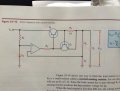
I have another question regarding material from Electronic Principles (page 960). I attached an image to better illustrate.
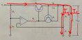
In discussing current limiting with respect to a series regulator, the book states that the load current has to pass through R4. Is this correct, or just that most of the load current passes through R4?
The book goes on to say that R5 is added to increase the output impedance of the op amp. Also, the value of R5 is selected to be high enough to produce voltage gain in the current-sensing transistor, but not so high that it prevents the op amp from driving the pass transistor.
It makes sense to me that with any changes in current through Q1, a larger R5 will create a greater and therefore faster/more sensitive voltage response. However, I dont understand why this would impact the op amps ability to drive the pass transistor.
I really appreciate everyones help.
Austin
I have another question regarding material from Electronic Principles (page 960). I attached an image to better illustrate.
In discussing current limiting with respect to a series regulator, the book states that the load current has to pass through R4. Is this correct, or just that most of the load current passes through R4?
The book goes on to say that R5 is added to increase the output impedance of the op amp. Also, the value of R5 is selected to be high enough to produce voltage gain in the current-sensing transistor, but not so high that it prevents the op amp from driving the pass transistor.
It makes sense to me that with any changes in current through Q1, a larger R5 will create a greater and therefore faster/more sensitive voltage response. However, I dont understand why this would impact the op amps ability to drive the pass transistor.
I really appreciate everyones help.
Austin